Driving gear shaft for gearbox

A technology for driving gear shafts and gearboxes, which is applied in the directions of gear lubrication/cooling, shafts, shafts, and bearings, and can solve problems such as uneven pressure distribution in oil grooves, and achieve the effect of improving press-fit quality and avoiding relaxation problems

Inactive Publication Date: 2013-01-02
ZHUZHOU ELECTRIC LOCOMOTIVE CO LTD
View PDF10 Cites 5 Cited by
  • Summary
  • Abstract
  • Description
  • Claims
  • Application Information

AI Technical Summary

Problems solved by technology

[0006] In order to overcome the disadvantage that the oil groove and the oil hole on the driving gear shaft of the gearbox of the existing urban rail transit vehicle adopt the above-mentioned structure, and there is no special oil groove for the uneven pressure distribution that may occur, the present invention aims to provide a The driving gear shaft of a gearbox, by adding a spiral oil groove on the driving gear shaft, the pressure between the mating surfaces can be evenly distributed when the coupling is assembled and disassembled, and the above problems can be avoided

Method used


Image

  • Driving gear shaft for gearbox
  • Driving gear shaft for gearbox
  • Driving gear shaft for gearbox

Examples


Embodiment Construction

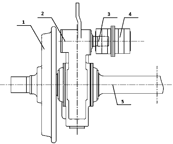
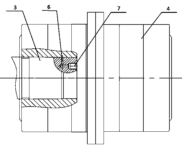
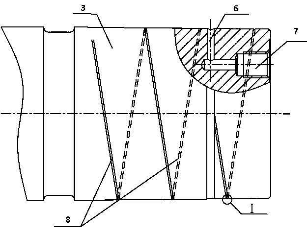
[0026] A gearbox driving gear shaft, such as image 3 As shown, it includes a driving gear shaft 3 connected with an interference fit with the coupling 4; the outer circular surface of the driving gear shaft 3 is provided with a U-shaped spiral oil groove 8 in section, as figure 2 As shown, the outer circular surface of the driving gear shaft 3 is used to cooperate with the inner surface of the shaft coupling 4 . Such as image 3 As shown, the spiral oil groove 8 communicates with the oil groove 6 and is distributed at equal intervals in the axial direction. Such as Figure 4 As shown, the helical oil groove 8 is continuous on the surface of the driving gear shaft 3, and the helical oil groove 8 is chamfered in order to avoid stress concentration at sharp corners.

[0027] The pitch of the helical oil groove 8 is 1 / 3 of the mating length of the coupling 4 and the driving gear shaft, because the pitch is too large, the processing technology is complicated, and it is not con...


PUM


Abstract

The invention discloses a driving gear shaft for a gearbox. In order to solve the problems that relaxation is generated between a driving gear shaft and a coupling when a gearbox of the conventional urban mass transit vehicle works and the matching surface is scratched in the process of mounting and dismounting the coupling, the shaft end face of the driving gear shaft for the gearbox is provided with an oil injection hole; an oil groove communicated with the oil injection hole is formed in the outer circumferential surface of the driving gear shaft; a spiral oil groove is formed in the outer circumferential surface of the driving gear shaft; and the spiral oil groove is communicated with the oil groove. The spiral oil groove is machined in a matching part of the gear shaft and the coupling, the press fitting quality of the coupling is greatly improved, the possible problem of relaxation between the coupling the driving gear shaft is solved, and the phenomenon that no scratch exists between the matching surfaces is ensured in the process of detaching the coupling.

Description

technical field [0001] The invention relates to the design field of an oil groove on a gear box driving gear shaft, in particular to a gear box driving gear shaft. Background technique [0002] Such as figure 1 As shown, on an urban rail transit vehicle, the input torque is transmitted to the driving gear shaft 3 through the coupling 4, and then transmitted to the axle 5 by the gearbox 2, and the wheel 1 is rotated by the reaction force of the track to realize the operation of the vehicle. Such as figure 2 As shown, the driving gear shaft 3 of the gearbox 2 and the coupling 4 widely adopt the interference fit method, and the necessary interference is generated on the mating surface through the taper and the axial position to realize the connection and transmit torque. [0003] The assembly method of the interference connection adopts the press-in method. When installing and disassembling the coupling on the driving gear shaft, it is necessary to inject high-pressure oil b...

Claims


Application Information

Patent Timeline
Patent Type & Authority Applications(China)
IPC IPC(8): F16C3/02F16H57/04
Inventor 陈喜红蒲全卫李冠军申长宏
Owner ZHUZHOU ELECTRIC LOCOMOTIVE CO LTD
Why Eureka
Try Eureka