Stamped support for solar heat-collecting power generation system

A solar heat collection and power generation system technology, applied in the field of stamping supports, can solve the problems of loose bolt connection and insufficient bearing strength, and achieve the effects of easy installation, high bearing strength and good rigidity

Inactive Publication Date: 2013-01-02
HARBIN TURBINE
View PDF4 Cites 8 Cited by
  • Summary
  • Abstract
  • Description
  • Claims
  • Application Information

AI Technical Summary

Problems solved by technology

[0003] The purpose of the present invention is to solve the problem that the existing bracket used to support the reflector is a part connected by multi-component bolts. Under

Method used


Image

  • Stamped support for solar heat-collecting power generation system
  • Stamped support for solar heat-collecting power generation system
  • Stamped support for solar heat-collecting power generation system

Examples


specific Embodiment approach 1

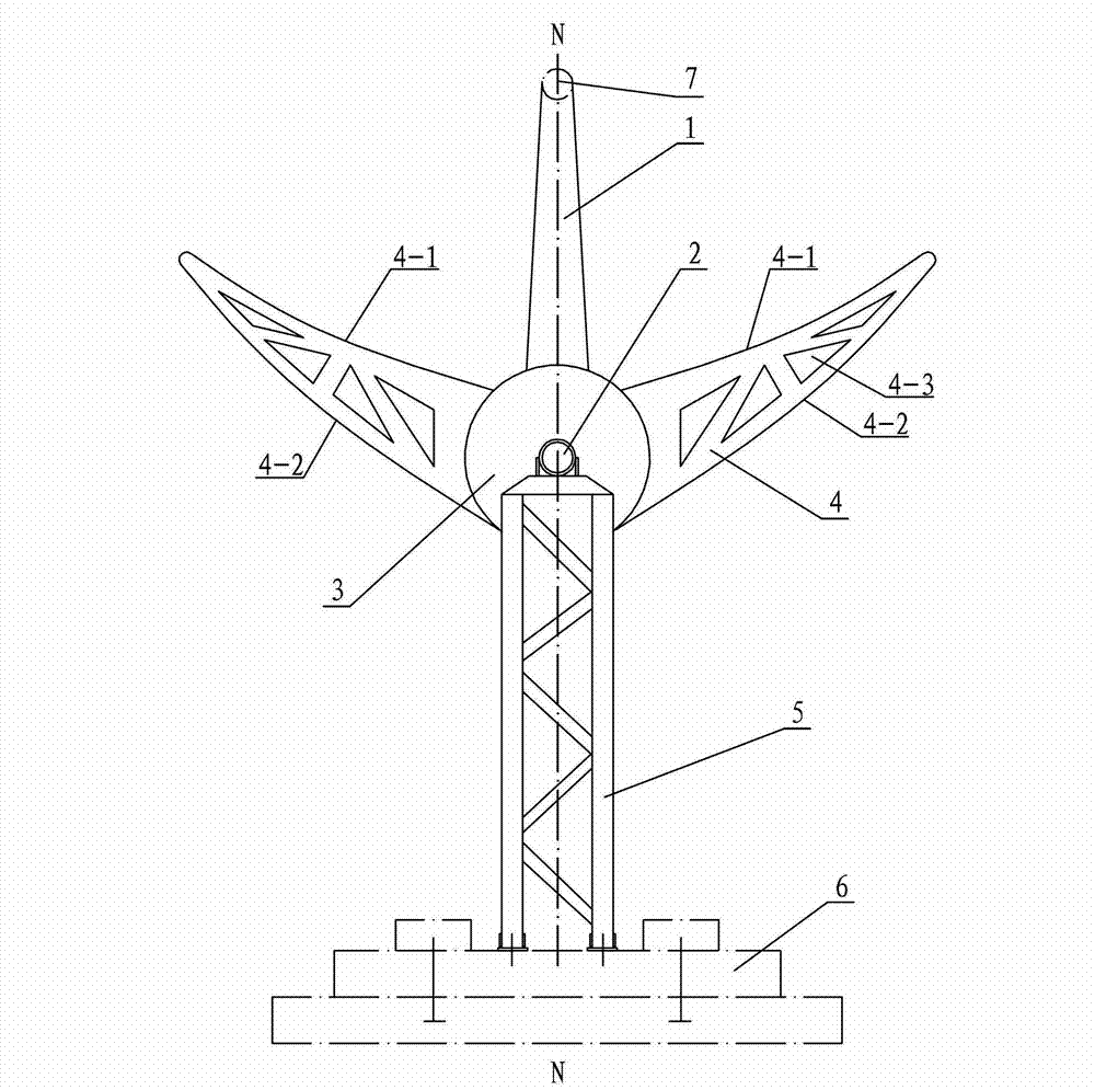
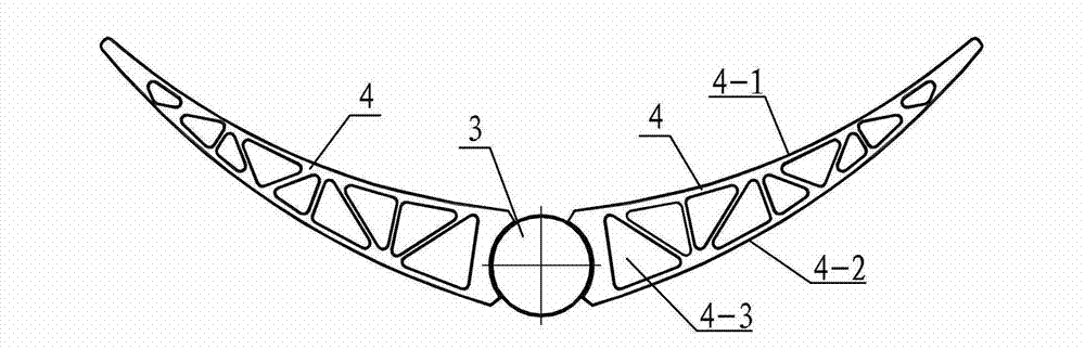
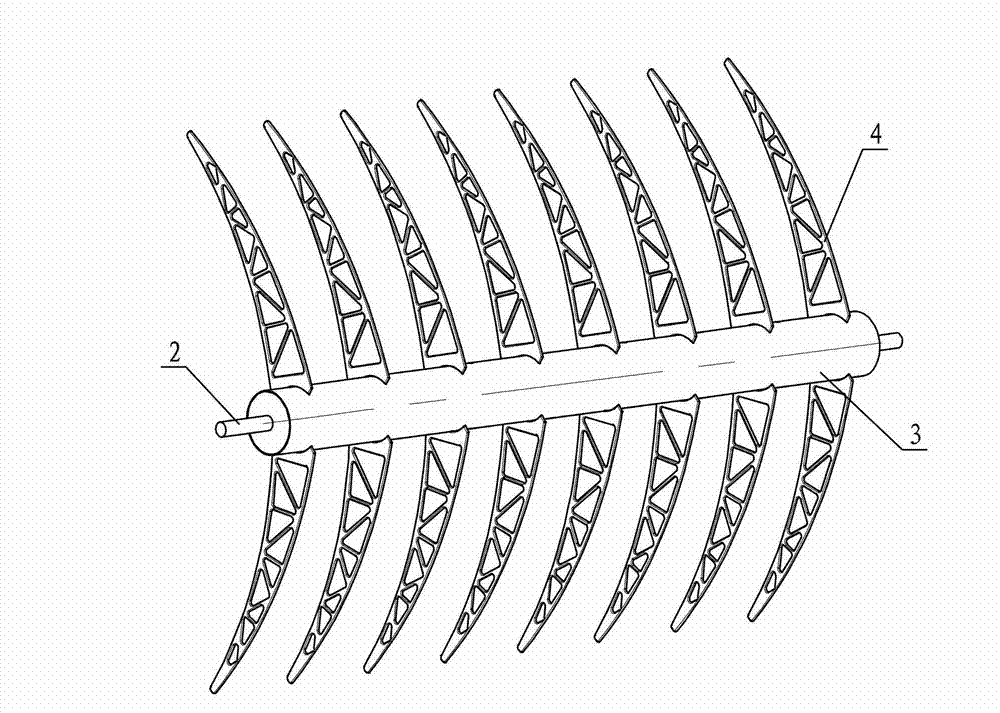
[0012] Specific implementation mode one: combine Figure 1 ~ Figure 3 Describe this embodiment, the stamping bracket of this embodiment includes a rotating tube 3, two fixed shafts 2, two supporting tower bridges 5, at least sixteen stamping cantilevers 4 and several heat collecting tube supports 1, and the two fixed shafts 2 are symmetrical Welded at the axis of both ends of the rotating tube 3, the lower end of each fixed shaft 2 is equipped with a supporting tower bridge 5, the fixed shaft 2 is set in the rolling bearing 5-1 on the supporting tower bridge 5, and the upper end of each stamping cantilever 4 The end surface is an inner concave arc surface 4-1, the lower end surface of the stamping cantilever 4 is an outward convex arc surface 4-2, one end of the stamping cantilever 4 is narrower than the other end, and at least sixteen stamping cantilevers 4 are divided into eight groups, each Two sets of stamping cantilevers 4, eight sets of stamping cantilevers 4 are evenly ...

specific Embodiment approach 2

[0013] Specific implementation mode two: combination Figure 4 Describe the present embodiment, the support tower bridge 5 of the present embodiment is made of rolling bearing 5-1, transverse connection plate 5-2, support ring seat 5-3, two support rods 5-4, two support rod bases 5-5 and Several reinforcing ribs 5-6 are formed, and the transverse connecting plate 5-2 is arranged on the upper ends of two supporting rods 5-4 arranged in parallel, and the transverse connecting plate 5-2 is fixedly connected with the supporting rod 5-4, and the supporting ring seat 5- 3 is fixed on the upper end surface of the transverse connecting plate 5-2, the rolling bearing 5-1 is fixed on the support ring seat 5-3, and a support rod base 5-5 is installed on the bottom of each support rod 5-4, several The reinforcing ribs 5-6 are alternately arranged along the two supporting rods 5-4, and the two ends of the reinforcing ribs 5-6 are respectively welded to the corresponding supporting rods 5-4...

specific Embodiment approach 3

[0014] Specific implementation mode three: combination Figure 5 Describe this embodiment, the heat collecting tube support 1 of this embodiment consists of an upper clamping arc plate 1-1, a lower supporting arc plate 1-2, a channel plate 1-3, a rigid support seat 1-4, and two rigid supports 1 -5 and two connecting pins 1-6, the upper clamping arc plate 1-1 and the lower support arc plate 1-2 are fastened and set, and the upper clamping arc plate 1-1 and the lower support arc plate 1-2 The inner hole is used to install the vacuum heat collecting tube 7, and the upper clamping arc plate 1-1 and the lower supporting arc plate 1-2 are set in the groove of the grooved plate 1-3, and the lower supporting arc plate 1- The two ends of 2 are respectively hinged to the side wall of the grooved plate 1-3 through two connecting pins 1-6, two rigid supports 1-5 and above clamp the centerline N-N of the arc plate 1-1 symmetrically arranged, and the rigid support 1 The upper end of -5 is ...


PUM


Abstract

The invention discloses a stamped support for a solar heat-collecting power generation system, and relates to a support. The stamped support aims to solve the problem that an existing support for supporting reflectors is an assembly with multiple components connected with one another by bolts, and is insufficient in bearing strength when used under severe conditions with strong wind and the like, and bolt connection positions of the existing support are easy to loose. The stamped support is characterized in that two fixed shafts are symmetrically welded at two axial positions of two ends of a rotating tube, a supporting tower bridge is assembled at the lower end of each fixed shaft, the fixed shafts are arranged in rolling bearings on the supporting tower bridges, the upper end surface of each stamped cantilever is an inwards concave arc-shaped surface, the lower end surface of each stamped cantilever is an outwards concave arc-shaped surface, one end of each stamped cantilever is narrower than the other end of the stamped cantilever, the at least sixteen stamped cantilevers are divided into eight groups, each group comprises two stamped cantilevers, the eight groups of cantilevers are uniformly arranged along the length direction of the rotating tube, the two stamped cantilevers in each group are symmetrically arranged on two sides of the rotating tube, the wide ends of the stamped cantilevers are fixedly connected with the rotating tube, and a plurality of heat-collecting tubes are uniformly disposed along the length direction of the rotating tube. The stamped support is used for solar heat-collecting power generation systems.

Description

technical field [0001] The invention relates to a support for a heat collection power generation system, in particular to a stamping support for a solar heat collection power generation system. Background technique [0002] The stamping support is the bearing part of the solar thermal power generation system, mainly supporting the reflector and the vacuum heat collecting tube. The existing bracket used to support the reflector and the vacuum heat collection tube is a multi-member bolted part. Under harsh conditions such as strong winds, the bearing strength is not enough, and the bolt connection is prone to loosening, causing deformation and damage to the reflector, thereby affecting solar heat collection. The performance of the power generation system, or even destroy the thermal power generation system. At the same time, the bolt connection also increases the installation process and increases the complexity of the bracket connection. Contents of the invention [0003]...

Claims


Application Information

Patent Timeline
IPC IPC(8): F24J2/52
CPCY02E10/47
Inventor 吕智强鞠凤鸣吕光阳崔贤基孙志强腾飞郭丽萍
Owner HARBIN TURBINE
Why Eureka
Try Eureka