Apparatus and method for detecting flatness

The technology of a detection device and detection method, which is applied in the field of optical measurement, can solve the problems of time-consuming and large amount of calculation, and achieve the effect of small amount of calculation and short detection time

Active Publication Date: 2013-01-02
SHENZHEN INST OF ADVANCED TECH
View PDF7 Cites 36 Cited by
  • Summary
  • Abstract
  • Description
  • Claims
  • Application Information

AI Technical Summary

Problems solved by technology

[0004] At present, most of the detection systems for workpiece flatness are based on 3D models, resulting in a large amount of calculation and time-consuming

Method used


Image

  • Apparatus and method for detecting flatness
  • Apparatus and method for detecting flatness
  • Apparatus and method for detecting flatness

Examples


Embodiment Construction

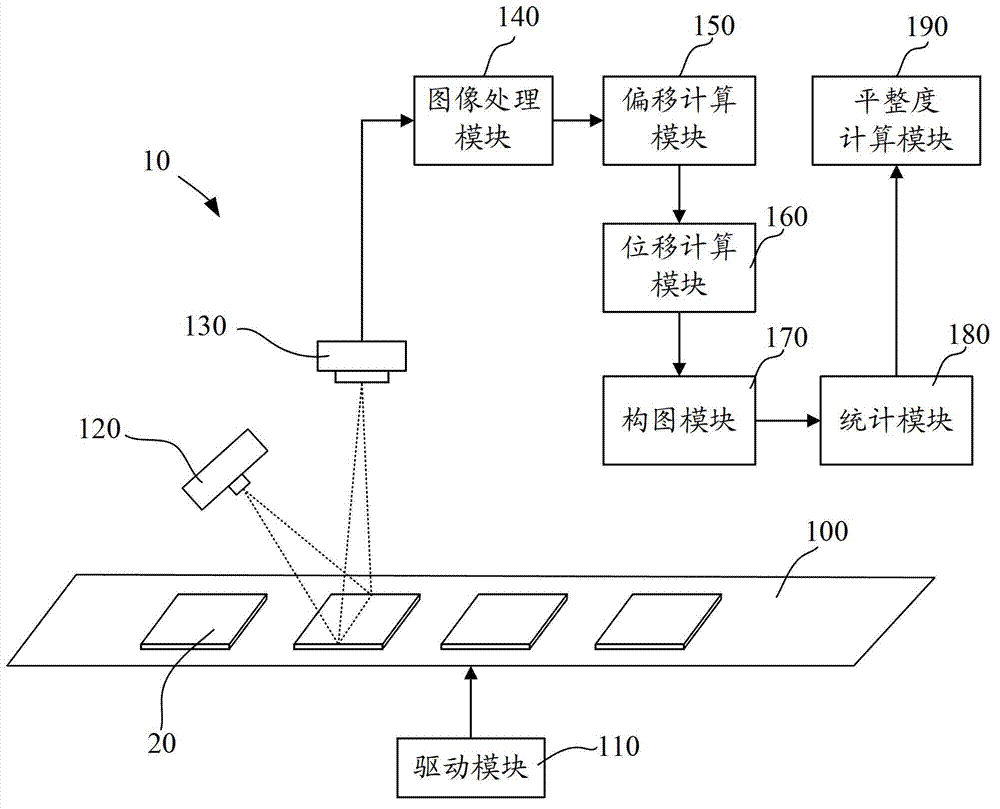
[0043] Such as figure 1 As shown, it is a schematic structural diagram of the flatness detection device 10 of an embodiment. It includes: carrying platform 100 , drive module 110 , laser module 120 , sensor module 130 , image processing module 140 , offset calculation module 150 , displacement calculation module 160 , composition module 170 , statistics module 180 and flatness calculation module 190 .

[0044] The carrying platform 100 is used for carrying the object 20 to be inspected.

[0045] The driving module 110 is used to drive the carrying platform 100 to move, so as to drive the object 20 to be inspected to move.

[0046] The laser module 120 is used for emitting a linear laser to the carrying platform 100 . That is, when the object 20 to be inspected is placed on the carrying platform 100 , the linear laser is irradiated on the surface of the object 20 to be inspected.

[0047] The sensing module 130 is used to acquire a plurality of inspection images of the linea...


PUM


Abstract

The invention discloses an apparatus for detecting flatness, which comprises a laser module for emitting linear laser, a sensing module which is used for acquiring multiple detecting images when the laser radiates on different positions of an object to be detected, an image processing module which is used for obtaining multiple laser images, an offset calculating module which is used for calculating image offsets of multiple points on the laser images corresponding to a preset reference surface, a displacement calculating module which is used for calculating the actual offset according to the image offsets and a preset algorithm, a figure forming module which is used for establishing waveform figures corresponding to the various laser images according to the actual offsets, a calculating module which is used for adding the multiple waveform figures to obtain a detecting curve, a flatness calculating module which is used for comparing the detecting curve with a preset standard carve to obtain the flatness of the object to be detected. Furthermore, the invention discloses a corresponding method. According to the apparatus and the method, the flatness can be detected by the optical principle and simple three-dimensional shaping data treatment. Compared with the conventional technology, the apparatus and the method are less in calculation amount and shorter in detection duration.

Description

technical field [0001] The invention relates to optical measurement technology, in particular to a flatness detection device and method. Background technique [0002] The measurement of object shape has a strong demand in the field of industrial manufacturing, especially the non-contact measurement method, which has a wide range of applications in precision manufacturing, aerospace, military and many other fields. The measurement of object shape can be divided into contact and non-contact measurement methods. Contact measurement is the contact measurement between the measuring head and the surface of the workpiece, and the scanning movement along the shape of the workpiece. Its disadvantage is that it is easy to cause different degrees of damage to the surface to be tested. Due to the development of laser measurement technology, non-contact measurement methods have become mainstream. [0003] There is an ultra-high-speed real-time three-dimensional visual measurement devi...

Claims


Application Information

Patent Timeline
Patent Type & Authority Applications(China)
IPC IPC(8): G01B11/30
Inventor 程俊陶大程沈三明姜军
Owner SHENZHEN INST OF ADVANCED TECH
Why Eureka
Try Eureka