Commodity storage device for vending machine

A technology of automatic vending machines and storage devices, applied in the direction of coin-free or similar appliances, coin-operated equipment for distributing discrete items, and coin-operated equipment for distributing discrete items, which can solve the problem of increased material costs and work Increased working hours etc.

Active Publication Date: 2013-01-02
FUJI ELECTRIC CO LTD
8 Cites 11 Cited by

AI-Extracted Technical Summary

Problems solved by technology

If the thickness of the passage width limiting plate 7 is increased, the material cost will increase, and it is difficul...

Abstract

The invention provides a commodity storage device for a vending machine, allowing thinning of a channel width limiting plate and compensating the mechanical strength of an engagement shaft by a material with a prescribed size. The commodity storage device comprises a channel width limiting plate (7A), which is configured opposite to a commodity discharging mechanism. An engagement shaft (71, 71) protruding from left and right ends of a substrate (70) is inserted through setting grooves (51a, 51b) of a frame-side plate (51) and is capable of freely moving between an entry position for entering into a commodity channel and a retreat position for retreating from the commodity channel. A protruding part (72) protruding towards the commodity channel is formed by bending at a position substantially opposite to a pedal on the commodity discharging mechanism. An engaging shaft part (73) is arranged on the channel width limiting plate (7A), is connected with a bending part (731) which connects the tabulate substrate (70) and the protruding part (72), and protrudes from the channel width limiting plate (7A) to the side. Deformation is prevented even in the condition of thinning of the channel width limiting plate (7A).

Application Domain

Coin-freed apparatus detailsApparatus for dispensing discrete articles

Technology Topic

Channel widthThinning +4

Image

  • Commodity storage device for vending machine
  • Commodity storage device for vending machine
  • Commodity storage device for vending machine

Examples

  • Experimental program(1)

Example Embodiment

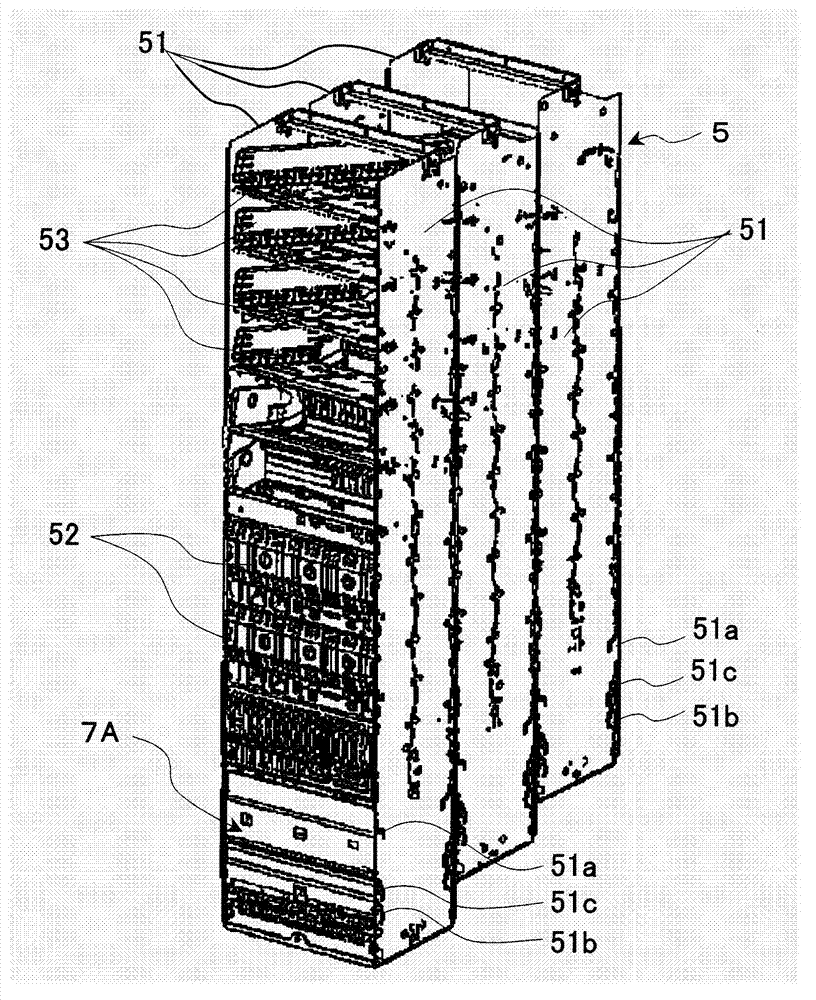
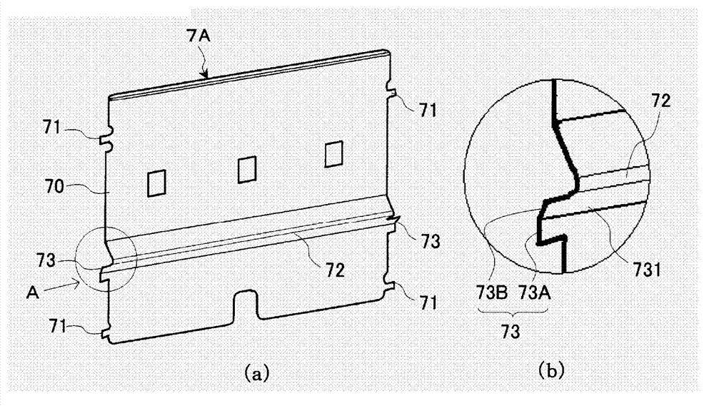
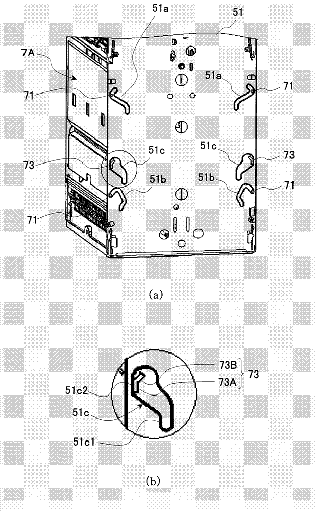
[0042] Hereinafter, a product storage device for an automatic vending machine according to an embodiment of the present invention will be described with reference to the drawings. In addition, the similarities and differences between the commodity storage device of the automatic vending machine in the embodiment of the present invention and the existing device are mainly the passage width limiting plate 70, because the overall structure of the automatic vending machine is different from that of the existing device. Figure 4 The same as shown, in addition, the composition of the product output device 6 is the same as Image 6 are the same as shown, so it is appropriate to refer to Figure 4 and Image 6 Be explained.
[0043] figure 1 Among them, 5 is a product storage rack, which has a pair of left and right frame side plates 51, 51, and on the left and right pair of frame side plates 51, 51, an arc-shaped bow frame 52 is connected and erected in the vertical direction. By linking the above-mentioned bow-shaped frames 52 in the up-down direction, the bow-shaped columns formed by staggering the half-pitch front and back are relatively arranged, and the commodity passages 50 snaking in the up-down direction are divided (refer to Figure 4 ), the top tray 53 is laid in such a way as to connect the passage entrance at the upper end of the above-mentioned commodity passage 50 with the front opening (commodity input port) of the main cabinet 1, and on the other hand, at the outlet at the lower end of the above-mentioned commodity passage 50, to sandwich Commodity channel 50 relative mode configures commodity delivery mechanism 6 (referring to Figure 4 ) and channel width limiting plate 7A. In addition, the above-mentioned product channel 50 and the product delivery mechanism 6 are figure 1 The center is blocked by the frame side plate 51 and cannot be seen, but the commodity delivery mechanism 6 is as well known, and is configured in combination with the commodity delivery mechanism of the same structure back to back between the commodity passages 50 arranged in front and behind.
[0044] like figure 2 As shown, the channel width restricting plate 7A disposed opposite to the above-mentioned product delivery mechanism 6 and forming an inner wall of the product channel 50 is provided with engaging shafts 71 protruding sideways from the upper, lower, left, and right ends of the rectangular plate-shaped substrate 70 , 71. At the same time, it is equipped with the upper pedal 62 of the product delivery mechanism 6 (refer to Image 6 ) protrudes toward the commodity passage 50, and its front end (commodity locking part) is approximately opposite to the protruding portion 72 that protrudes toward the commodity passage 50. These aspects are consistent with Image 6 The existing installation shown is the same. This channel width limiting plate 7A differs from conventional devices in two points of material and structure. First of all, in terms of material, although it is made of a rectangular plate-shaped steel plate like the conventional device, a thin steel plate with a thinner steel plate thickness than the conventional device is used. That is, the channel width regulating plate 7 in the conventional device has a plate thickness of 5 mm, whereas the channel width regulating plate 7A of the first embodiment uses a thin steel plate of 3 mm. Next, secondly, in terms of structure, locking shaft portions 73 , 73 coupled to the above-mentioned protruding portion 72 and protruding laterally from the passage width limiting plate 7A are provided. The locking shaft portions 73, 73 will be described later. In addition, if image 3 As shown, the frame side plate 51 is provided with the upper and lower setting grooves 51a, 51b through which the upper and lower engaging shafts 71, 71 of the passage width limiting plate 7A are inserted, which is the same as the conventional device. The frame side plates 51, 51 are different from the conventional devices in that they are additionally provided with locking grooves 51c for inserting and supporting the locking shafts 73, 73, and the locking grooves 51c will be described later.
[0045] In addition, if figure 2 As shown, the locking shafts 73 and 73 of the channel width regulating plate 7A are formed to protrude laterally from the base plate 70 in a continuous manner with the bent portion 731 connecting the flat base plate 70 and the protruding portion 72 . It is constituted by a locking portion 73A formed of a plane along the vertical direction of the plate surface of the above-mentioned substrate 70 and an inclined portion 73B inclined obliquely upward. In this way, since the locking shaft portions 73 and 73 sandwich the bent portion 731, the locking portion 73A composed of a plane along the vertical direction of the board surface of the substrate 70 and an inclined portion inclined obliquely upward are used. 73B, so that the inclined portion 73B functions as a flange with respect to the locking portion 73A. Therefore, even when the locking shaft portions 73 and 73 are made of a thin steel plate, the mechanical strength can be improved.
[0046] like image 3As shown, the frame side plates 51 , 51 are additionally provided with locking grooves 51 c with respect to the locking shaft portions 73 , 73 of the passage width regulating plate 7A. The locking groove 51c is formed to be wider than the upper and lower setting grooves 51a, 51b through which the upper and lower engagement shafts 71, 71 of the passage width regulating plate 7A are inserted, and is equipped with the movement of the passage width regulating plate 7A to the entry position. (narrow width setting position) and the retreat position (wide width position) abut against the locking portion 73A of the locking shaft portion 73, 73 to prevent the rearward movement of the passage width limiting plate 7A and the first preventing portion 51c1 and The second blocking portion 51c2. The locking groove 51c is formed wider than the upper and lower setting grooves 51a, 51b in order to make the above-mentioned engaging shafts 71, 71 in the entry position (narrow width setting) along the locking grooves 51a, 51b by manual operation. position) or the retracted position (wide width position) to move forward and backward to set the channel width, the locking shafts 73, 73 do not come into contact with the edge of the locking groove 51c, thereby hindering the setting of the channel width. In addition, the first blocking portion 51c1 and the second blocking portion 51c2 of the above-mentioned locking groove 51c are formed so as to be located at respective ends connecting the front and rear (positions close to and distanced from the product delivery mechanism 6 ) of the lower setting groove 51b. part and the groove part extending up and down in the upper part of the adjustment groove 51a (the position close to and the position away from the product delivery mechanism 6 ) on the line.
[0047] The above passage width limiting plate 7A is the same as the conventional device, by inserting the upper and lower engagement shafts 71, 71 and the locking shaft portion 73 into the upper and lower setting grooves 51a formed in the pair of left and right frame side plates 51, 51, 51b and the locking groove 51c, and is supported between the frame side plates 51 in an upright posture, and the upper and lower engagement shafts 71, 71 are moved along the setting grooves 51a, 51b to the entry position (narrow width setting position) by manual operation. ) and the back position (wide position), thereby setting the channel width. The passage width regulating plate 7A of this embodiment is different from the conventional device in that the passage width regulating plate 7A is moved to the entry position (narrow width setting position) and the retreat position (wide width setting position) In this case, the locking portion 73A of the locking shaft portion 73 abuts on the first blocking portion 51c1 and the second blocking portion 51c2 of the locking groove 51c, respectively. image 3 The figure shows the state in which the channel width limiting plate 7A has moved to the retracted position (width setting position), and the locking shaft portion 73d and the locking portion 73A are in contact with the second blocking portion 51c2 of the locking groove 51c, and the image 3 When the upper and lower engaging shafts 71, 71 are moved to the entry position (narrow width setting position) along the setting grooves 51a, 51b by manual operation, the locking part 73A of the locking shaft part 73 and the locking The first stopper portion 51c1 of the groove 51c abuts against it.
[0048] In this way, when the passage width limiting plate 7A is moved to the entry position (narrow width setting position) and the retracted position (wide width position), the locking portion 73A of the locking shaft portion 73 is locked respectively. The first stopper portion 51c1 and the second stopper portion 51c2 of the check groove 51c contact each other, and the product load acting on the passage width regulating plate 7A acts concentratedly on the locking shaft portion 73 . The reason why the commodity load acts concentratedly on the locking shaft portion 73 is as follows. That is, if Image 6 As shown, the protruding portion 72 formed by bending on the passage width limiting plate 7 is formed on the upper pedal 62 toward the commodity passage in order to make the upper pedal 62 of the commodity delivery mechanism 6 reliably lock the next sales commodity G2. When 50 protrudes, its front end (commodity locking part) is approximately opposite to the position, and together with the product locking part of the upper pedal 62 protruding to the commodity channel 50, the next selling commodity G2 is locked. Therefore, in the aisle width regulating plate 7, the next selling product G2 and the product load superimposed thereon are intensively applied to the position of the protruding portion 72 where the next selling product G2 abuts. In addition, when the product is on standby, the product G1 is held in contact with the lower pedal 61 protruding toward the product channel 50 and the protruding portion 72 of the channel width limiting plate 7 or near the protruding portion 72. , the sales commodity G1 and the commodity load superimposed thereon are intensively applied to the protruding portion 72 where the commodity G1 abuts or its vicinity. In this way, since the protruding part 72 formed by bending on the channel width limiting plate 7 or the position near it is concentratedly applied with the product load, therefore, the lock shaft part 73 formed continuously with the protruding part 72 and the locking shaft part 73 formed on the frame side plate 51 When the first blocking portion 51c1 or the second blocking portion 51c2 of the locking groove 51c abuts against each other, the product load is intensively applied to the locking shaft portion 73 .
[0049] In this way, when the product load is intensively applied to the above-mentioned locking shaft portion 73, deformation occurs when the rigidity of the locking shaft portion 73 becomes weak. However, the locking shaft portion 73 of the present invention is connected with the The base plate 70 is connected to the bent portion 731 of the protruding portion 72 and protrudes laterally from the base plate 70 , which has high mechanical strength and thus is not deformed by the product load. Moreover, since the locking portion 73A of the locking shaft portion 73 abuts against the first blocking portion 51c1 or the second blocking portion 51c2 of the locking groove 51c, most of the product load acting on the channel width limiting plate 7A is received, Therefore, almost no product load is applied to the upper and lower engaging shaft portions 71 , 71 of the passage width regulating plate 7A. Therefore, the upper and lower engagement shafts 71, 71 only need to realize the function of the guide when the passage width limiting plate 7A is placed in the entry position (narrow width setting position) and the retreat position (wide width setting position), When the passage width regulating plate 7A is formed of a thin steel plate, there is no problem with the mechanical strength of the upper and lower engagement shafts 71 , 71 .
[0050] In addition, since the stacked state of the products stacked in the product channel 50 varies greatly, it is impossible to prevent the product load from acting on the upper and lower engaging shafts 71, 71 of the channel width limiting plate 7A, but the upper and lower engaging shafts The product load of 71 and 71 is small compared with the product load carried by the engaging shaft portion 72 . Therefore, even when the passage width regulating plate 7A is formed of a thin steel plate, the mechanical strength of the upper and lower engagement shafts 71 , 71 can be compensated.
[0051] As described above, according to the product storage device for an automatic vending machine of the present invention, the lower end of the product channel 50 formed between the pair of left and right frame side plates 51 is provided with the product delivery mechanism 6 and the product delivery mechanism 6 arranged oppositely across the product channel 50 . Passage width restricting plate 7A. The passage width restricting plate 7A inserts the upper and lower engaging shafts 71, 71 protruding laterally from the left and right ends of the flat base plate 70 into the upper and lower fittings formed on the frame side plate 51. In the fixed grooves 51a and 51b, the aisle width restricting plate 7A can move forward and backward freely between the entry position (narrow width setting position) entering the product aisle 50 and the retreat position (wide width setting position) retreating from the product aisle. , is supported in an upright posture at the entry position or retreat position, and a protruding portion 72 protruding toward the product passage 50 is formed by bending at a position substantially opposite to the upper pedal 62 of the product delivery mechanism 6 on the flat base plate 70 , in the commodity storage device of the automatic vending machine, the passage width limiting plate 7A has a bending portion 731 connecting the flat base plate 70 and the protruding portion 72 and protrudes laterally from the passage width regulating plate 7A, In addition, the locking shaft portion 73 formed by using a plane in the vertical direction along the plate surface of the above-mentioned substrate 70 as the locking portion 73A is formed on the frame side plate 51 with a locking groove 51c, and the locking groove 51c It is inserted and supported by the locking shaft portion 73, and has a locking portion 73A that comes into contact with the locking shaft portion 73 when the passage width limiting plate 7A moves between the advanced position and the retracted position to block the passage. The first preventing portion 51c1 and the second preventing portion 51c2 for the backward movement of the width limiting plate 7A, whereby the product load carried by the passage width limiting plate 7A is concentrated on the locking shaft portion 73, but since the locking shaft portion 73 has The bent portion 731 has high mechanical strength, so it will not be deformed by the product load. Accordingly, the product load applied to the aisle width limiting plate 7A can be shared with the locking shaft portion 73 , and the product load applied to the upper and lower engaging shafts 71 , 71 is extremely small. Therefore, the upper and lower engagement shafts 71, 71 only need to have a guide that guides the channel width limiting plate 7A to a predetermined position (narrow width setting position, wide width setting position) by moving along the setting grooves 51a, 51b. function. Therefore, even when the channel width regulating plate 7A is made thinner, the mechanical strength of the upper and lower engaging shafts 71 and 71 can be compensated by forming the locking shaft portion 73 connected to the protruding portion 72 provided on the channel width regulating plate 7A. .
[0052] In the above-mentioned embodiment, the locking shaft portion 73 of the passage width regulating plate 7A has been described as using the bent portion below the protrusion 72 , but the locking shaft portion 73 may also use the bent portion above the protrusion 72 . In addition, the shape of the locking groove 51c formed in the frame side plates 51, 51 is not limited to the illustrated shape, and the present invention is not limited to the above-mentioned embodiment.

PUM

no PUM

Description & Claims & Application Information

We can also present the details of the Description, Claims and Application information to help users get a comprehensive understanding of the technical details of the patent, such as background art, summary of invention, brief description of drawings, description of embodiments, and other original content. On the other hand, users can also determine the specific scope of protection of the technology through the list of claims; as well as understand the changes in the life cycle of the technology with the presentation of the patent timeline. Login to view more.
Why Eureka
Try Eureka