Shift register and electronic apparatus

Inactive Publication Date: 2009-03-24
ORTUS TECH
View PDF12 Cites 65 Cited by
  • Summary
  • Abstract
  • Description
  • Claims
  • Application Information

AI Technical Summary

Benefits of technology

[0007]It is an object of the present invention to provide a shift register which can obtain a correct

Problems solved by technology

On the other hand, since the structure of the gate driver is not very complicated as the drain electrode and the gate driver has a low dri

Method used


Image

  • Shift register and electronic apparatus
  • Shift register and electronic apparatus
  • Shift register and electronic apparatus

Examples


first embodiment

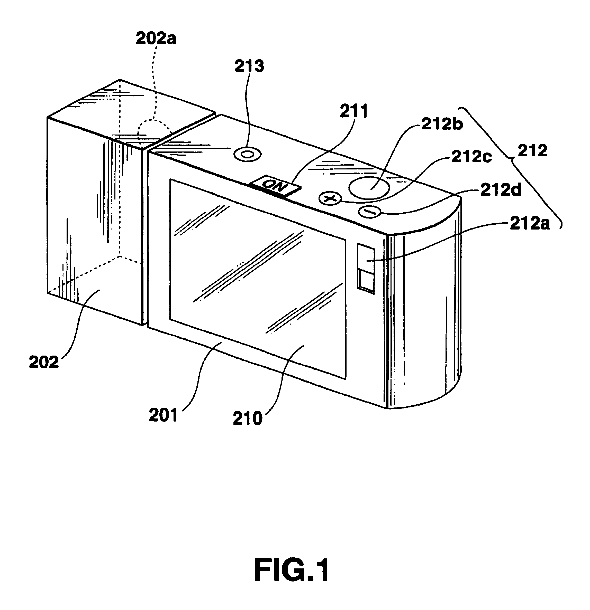
[0075]Preferred embodiments according to the present invention will now be described with reference to the accompanying drawings. FIG. 1 is a view showing an external appearance structure of a digital still camera according to this embodiment. As shown in the figure, this digital still camera is constituted by a camera main body portion 201 and a lens unit portion 202.

[0076]The camera main body portion 201 includes a display portion 210 and a mode setting key 212a in the front part thereof. The mode setting key 212a is a key used for switching between a recording mode for picking up an image and recording it in a later-described memory and a reproduction mode for reproducing the recorded image. The display portion 210 is constituted by a liquid crystal display. This portion functions as a view finder for displaying an image captured by a lens 202a before image pickup in the recording mode (monitoring mode) and functions as a display for displaying a recorded image in the reproductio...

second embodiment

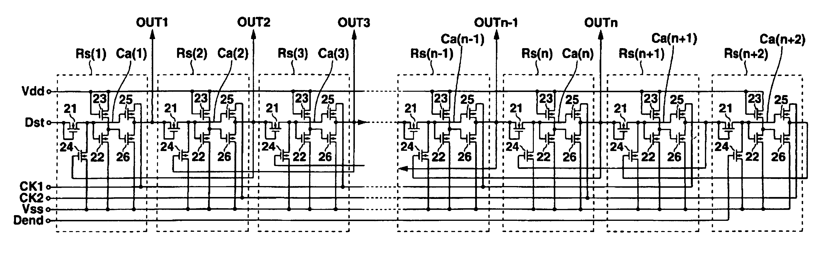
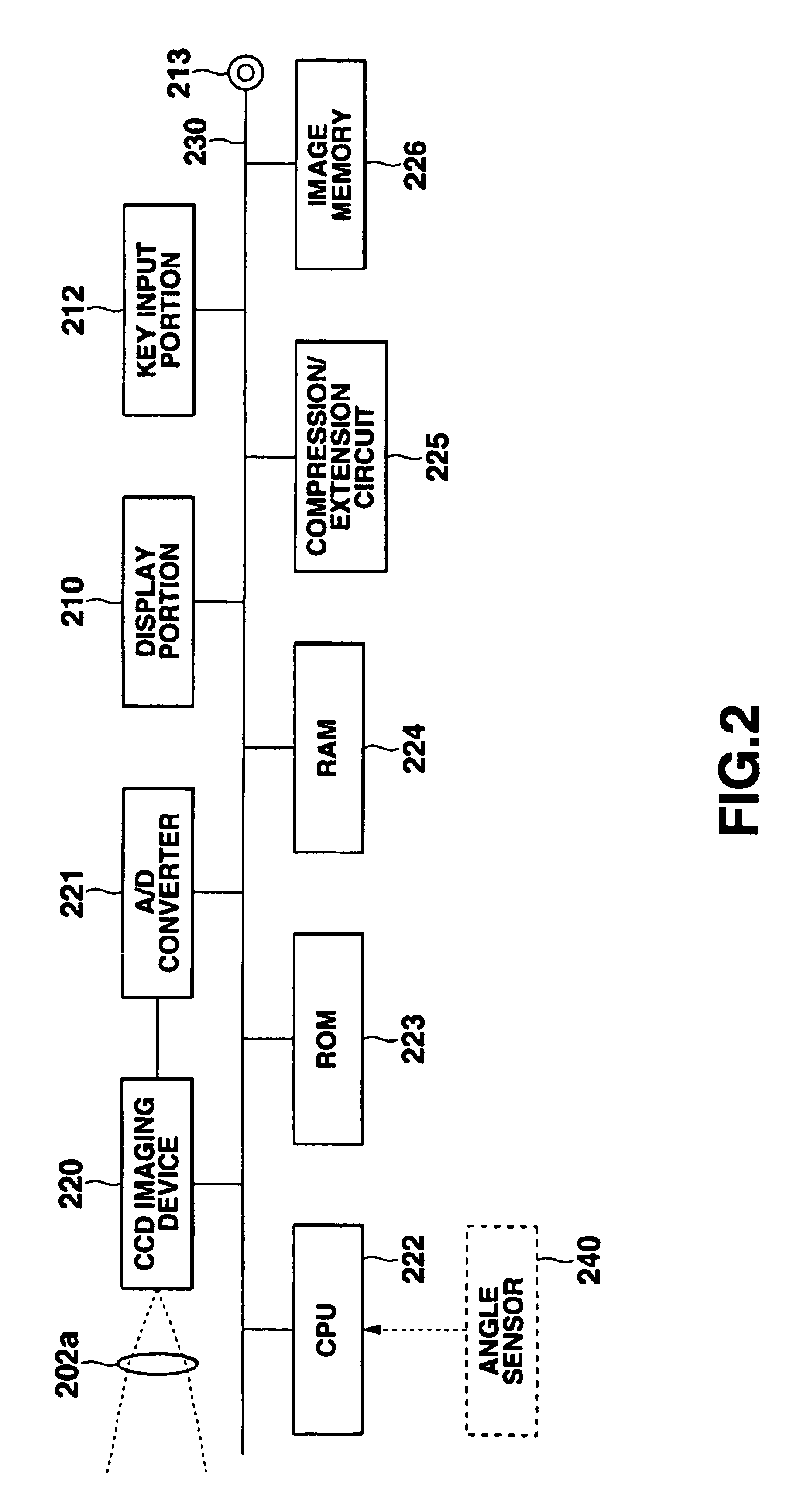
[0204]A digital still camera according to this embodiment is substantially the same as that according to the first embodiment but different from the foregoing embodiment in that an angle sensor 240 indicated by a dotted line in FIG. 2 is provided. In addition, a sift register applied as the gate driver 152 in the display portion 210 is different from the first embodiment, and a shift register which can shift an output signal in both forward and backward directions is used in this embodiment. Additionally, in this regard, signals outputted as the control signal group Gcnt from the controller 150 are also different slightly.

[0205]The angle sensor 240 detects an angle of a lens unit portion 202 with respect to a camera main body portion 201. A detection signal of the angle sensor 240 is inputted to a CPU 222, and the CPU 222 supplies to a display portion 210 a control signal which indicates that a display scanning direction (shift operation direction of the shift register applied as th...


PUM


Abstract

Each of stages RS(1), RS(2), . . . of a shift register is constituted by six TFTs. A ratio of a channel width and a channel length (W/L) of each of these TFTs 1 to 6 is set in accordance with a transistor characteristic of each TFT in such a manner that the shift register normally operates for a long time even at a high temperature.

Description

CROSS-REFERENCE TO RELATED APPLICATIONS[0001]This application is based upon and claims the benefit of priority from the prior Japanese Patent Applications No. 2000-162671, filed May 31, 2000; No. 2000-169002, filed Jun. 6, 2000; and No. 2001-128909, filed Apr. 26, 2001, the entire contents of all of which are incorporated herein by reference.BACKGROUND OF THE INVENTION[0002]The present invention relates to a shift register and an electronic apparatus such as a display unit or an imaging apparatus, using this shift register as a driver.[0003]In an active matrix type liquid crystal display such as a TFT liquid crystal display, each one line of display pixels arranged in the matrix form is selected, and display data is written in a pixel capacitance of the selected pixels, thereby obtaining desired display.[0004]In the TFT liquid crystal display, there are used a gate driver for serially outputting a gate signal for pixel selection to a gate of the TFT functioning as a pixel switching ...

Claims


Application Information

Patent Timeline
IPC IPC(8): G11C19/28G11C19/00G09G3/36
CPCG09G3/3677G09G2300/0408G09G2310/0281G11C19/00G11C19/28Y10S323/907G09G3/36
Inventor KANBARA, MINORUSASAKI, KAZUHIROMOROSAWA, KATSUHIKO
Owner ORTUS TECH
Why Eureka
Try Eureka