Method for establishing urban trunk platoon dispersion model based on running speed forecasting

A technology for urban arterial roads and modeling methods, which is applied in traffic control systems of road vehicles, special data processing applications, instruments, etc., and can solve the problem of inability to accurately predict the arrival pattern of the downstream end face fleet.

Active Publication Date: 2013-01-02
哈尔滨工业大学高新技术开发总公司
View PDF1 Cites 13 Cited by
  • Summary
  • Abstract
  • Description
  • Claims
  • Application Information

AI Technical Summary

Problems solved by technology

[0004] In order to solve the problem that the minimum vehicle speed, maximum vehicle speed and average vehicle speed setting in the existing fleet discrete model rely on the experience of engineers and cannot accurately predict the arrival pattern of the downstream end-face fleet, the present invention further proposes a discrete model of urban arterial road fleet based on running vehicle speed prediction modeling method

Method used


Image

  • Method for establishing urban trunk platoon dispersion model based on running speed forecasting
  • Method for establishing urban trunk platoon dispersion model based on running speed forecasting
  • Method for establishing urban trunk platoon dispersion model based on running speed forecasting

Examples


specific Embodiment approach 1

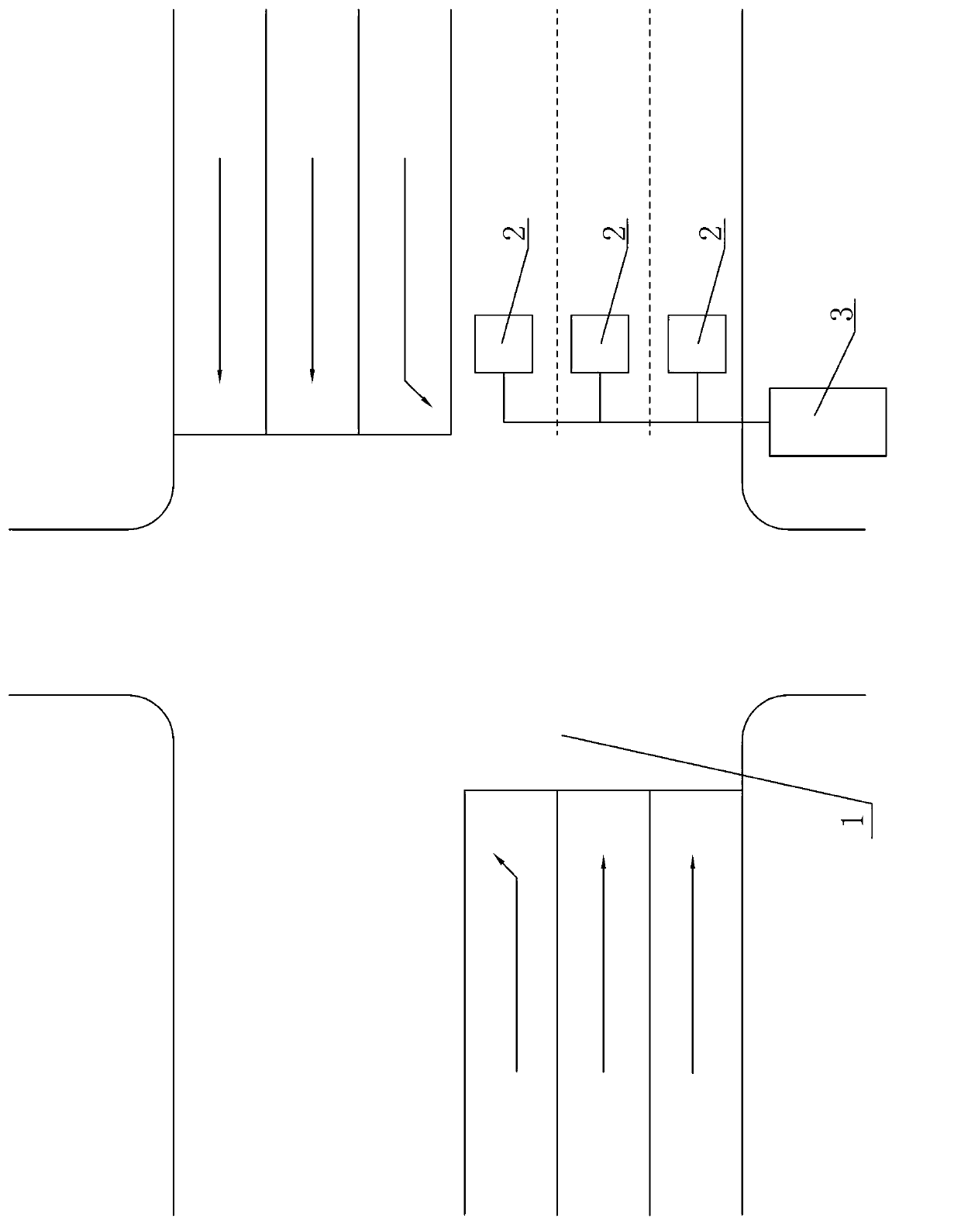
[0045] Specific implementation mode one: combine figure 1 Describe this embodiment, the specific steps of a kind of modeling method based on the discrete model of the urban arterial road vehicle fleet of running vehicle speed prediction described in this embodiment are as follows:

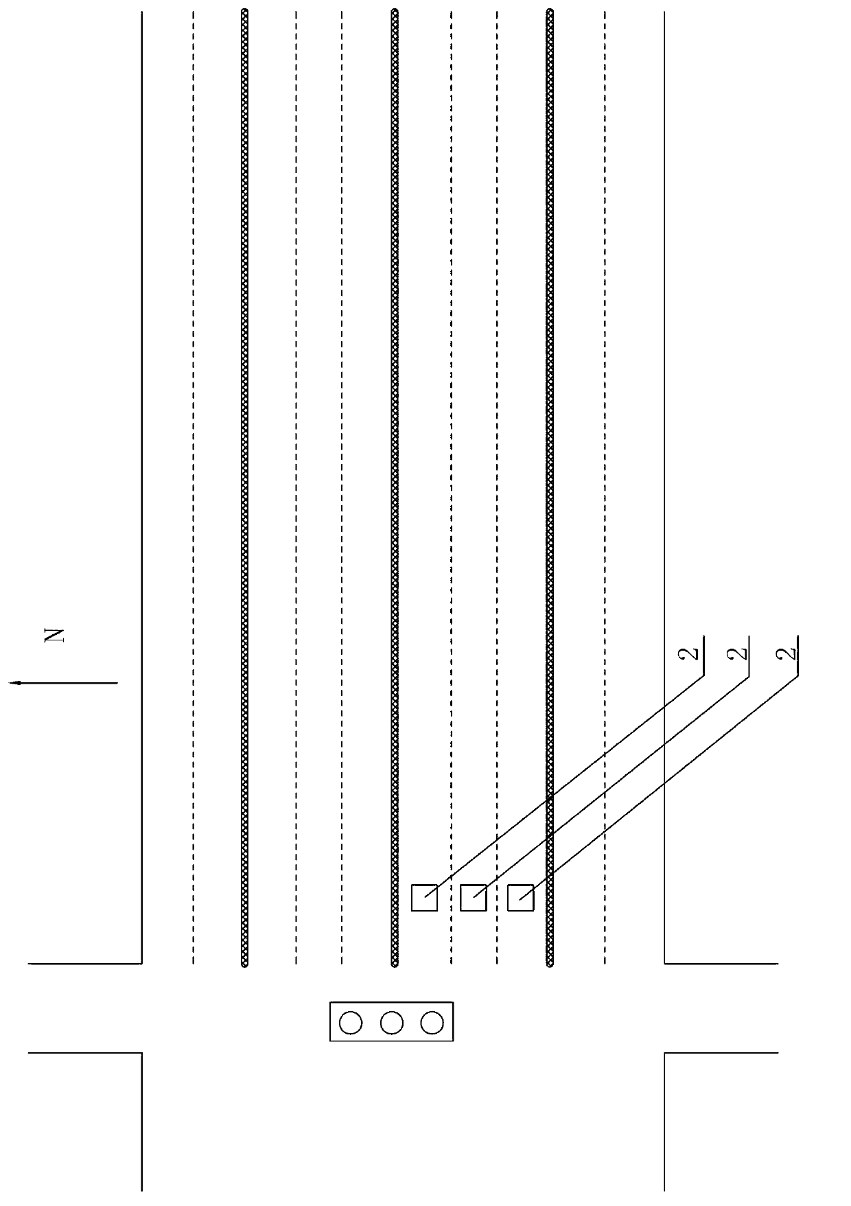
[0046] Step 1. An induction coil detector 2 is arranged on each lane downstream of the intersection exit on the main road 1 of the city, and each induction coil detector 2 is connected to the nearest traffic signal 3, and the signal 3 collects data from each motor vehicle. The pulse signal produced when passing through the rear end edge and the front edge of the induction coil detector 2, and then record the moment when each pulse signal is generated;

[0047] Step 2, identifying whether the motor vehicles passing through the induction coil detector 2 belong to the same convoy;

[0048] Step 3, calculate the highest speed, the lowest speed, the average speed in the same fleet, and predict the curren...

specific Embodiment approach 2

[0083] Specific implementation mode two: combination figure 1 Illustrate this embodiment, in the step one of the modeling method of the discrete model of urban arterial road fleet described in this embodiment based on the operation vehicle speed prediction, the length of each induction coil detector 2 is 2m, and the width is 2m, and each induction coil The detector 2 is set on the lane 30m-50m downstream of the exit of the signalized intersection, and the signal machine 3 records the time when each pulse signal is generated with an accuracy of 0.01 second. Other components and connections are the same as those in the first embodiment.

specific Embodiment approach 3

[0084] Specific implementation mode three: combination figure 1 Illustrate the present embodiment, the specific steps of identifying whether the motor vehicles passing through the induction coil detector 2 belong to the same fleet in the step 2 of the modeling method based on the discrete model of the urban arterial road fleet described in the present embodiment are:

[0085] Step 2 (1), judge whether a motor vehicle passes through the induction loop detector 2 rear end edge and its previous motor vehicle whether the moment difference is greater than 4 seconds through the induction coil detector 2 rear end edge, if greater than 4 seconds then this The two motor vehicles belong to different convoys, otherwise they belong to the same convoy;

[0086] Step 2 (two), classify the motor vehicles whose time difference between two consecutive motor vehicles passing the edge of the rear end of the induction coil detector 2 is less than 4 seconds into the same convoy. Other components ...


PUM


Abstract

The invention provides a method for establishing an urban trunk platoon dispersion model based on running speed forecasting, and relates to a method for establishing an urban trunk platoon dispersion model. With the adoption of the method provided by the invention, the problem of traditional platoon dispersion model that arriving chart of the platoon on the downstream end surface cannot be accurately forecasted by setting the minimum speed, the maximum speed and the average speed based on the experience of an engineer is solved. The method comprises the steps as follows: distributing sensing coil detectors on each driveway at the downstream of an outlet of an intersection of the urban trunk; and detecting the time of each motor vehicle in each platoon crossing the front ends and the rear ends of the sensing coil detectors through the sensing coil detectors, so as to establish the urban trunk platoon dispersion model. The method provided by the invention is suitable for establishing the urban trunk platoon dispersion model.

Description

technical field [0001] The invention relates to a modeling method for a discrete model of an urban arterial road fleet, in particular to a modeling method for a discrete model of an urban arterial road fleet based on running vehicle speed prediction. Background technique [0002] At present, the traffic conditions in major cities in my country are deteriorating day by day, which seriously hinders the development of social economy. As a modern traffic management method, traffic signal control technology can effectively improve the efficiency of road network traffic flow operation. In particular, by implementing signal coordination control on several adjacent intersections, traffic delays and parking times on arterial roads can be greatly reduced. In order to optimize the best signal coordination control scheme, the traffic control system must accurately predict the arrival of traffic at downstream intersections. [0003] When the fleet on the arterial road is running downstr...

Claims


Application Information

Patent Timeline
Patent Type & Authority Applications(China)
IPC IPC(8): G08G1/00G08G1/042G06F19/00
Inventor 别一鸣裴玉龙王琳虹孙烨
Owner 哈尔滨工业大学高新技术开发总公司
Why Eureka
Try Eureka