Cam controller with mechanical limit, forced disconnection and dynamic monitoring functions

A cam controller and dynamic monitoring technology, applied in the direction of contact drive mechanism, etc., can solve the problems of poor reliability, output shaft breakage, safety accidents, etc., and achieve the effect of stable installation structure and not easy to break

Active Publication Date: 2013-01-02
WUXI TUOFA AUTOMATIC CONTROL EQUIP
View PDF4 Cites 12 Cited by
  • Summary
  • Abstract
  • Description
  • Claims
  • Application Information

AI Technical Summary

Problems solved by technology

However, the existing cam controller generally does not have a dynamic monitoring device. After the cam controller fails (such as shaft breakage, switch failure), the press cannot be stopped in time, which may cause a safety accident.
[0006] In the existing cam controller, the encoder or resolver is generally installed with a shaft coupling, or an ordinary output shaft is used to connect the encoder or resolver. These two installation structures have the following two disadvantages: (1) Using a shaft coupling The shaft structure is relatively complex and the reliability is relatively poor; (2) The encoder or resolver connected with the ordinary output shaft, because the output shaft is thin, if there is a deviation during installation, or the output shaft is prone to breakage under high vibration conditions

Method used


Image

  • Cam controller with mechanical limit, forced disconnection and dynamic monitoring functions
  • Cam controller with mechanical limit, forced disconnection and dynamic monitoring functions
  • Cam controller with mechanical limit, forced disconnection and dynamic monitoring functions

Examples


Embodiment Construction

[0057] The present invention will be further described below in conjunction with specific drawings.

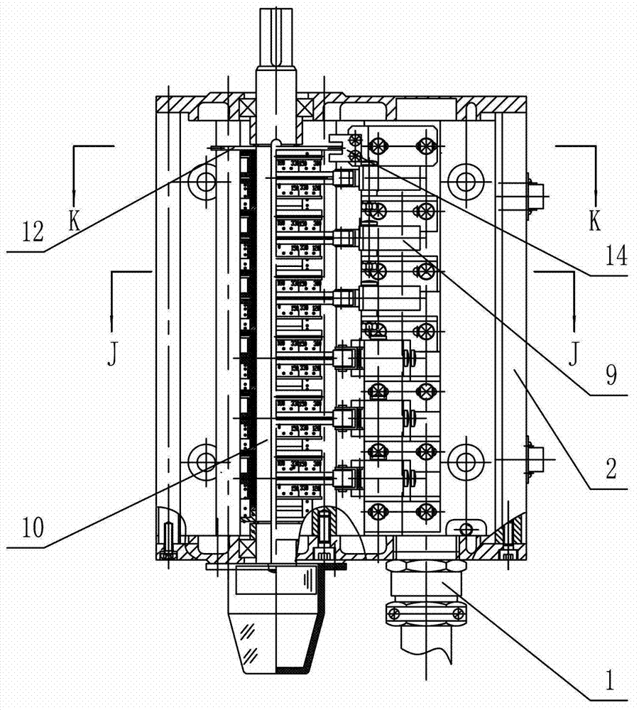
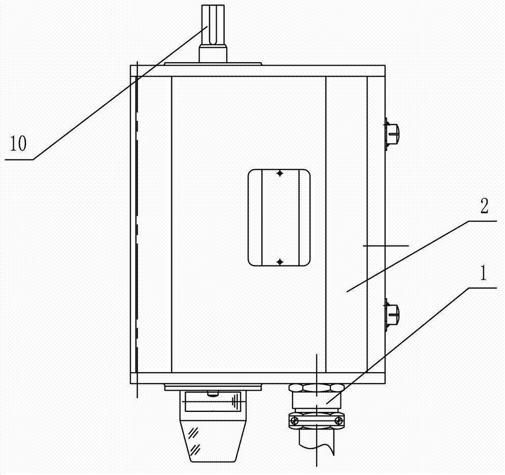
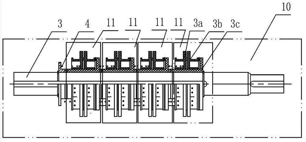
[0058] Such as Figure 1~Figure 30 Shown: The cam controller with mechanical limit, forced disconnection and dynamic monitoring includes cable terminal joint 1, controller cover 2, camshaft 3, compression spring 4, first limit device 5, second limit device 6. The third limit device 7, the fourth limit device 8, the switch 9, the camshaft assembly 10, the cam assembly 11, the code disc 12, the mounting bracket 13, the photoelectric sensor 14, the switch bracket 15, the resolver 16, the spring leaf 17. Coupling 18, output shaft 19, mounting flange 20, outer cam piece 3a, inner cam piece 3b, bushing 3c, first arc-shaped stopper 51, second arc-shaped stopper 61, third arc-shaped stopper Stopper 71, fourth arc-shaped stopper 81, first limit pin 52, second limit pin 62, first arc-shaped groove 72, second arc-shaped groove 82, third arc-shaped groove 53, fourth arc-shaped groove sh...


PUM


Abstract

The invention relates to a cam controller with mechanical limit, forced disconnection and dynamic monitoring functions. The cam controller comprises a cam shaft; cam assemblies are arranged on the cam shaft; a pressure spring is arranged between adjacent cam assemblies; each cam assembly comprises a shaft housing, an external cam sheet and an internal cam sheet; each group of the cam assemblies is correspondingly provided with a switch; the cam controller is characterized in that in at least two groups of cam assemblies, the internal sides of two end surface gear rings of the internal cam sheet are provided with a first limit device and a second limit device; the internal side of the end surface gear ring of the external cam sheet is provided with a third limit device capable of rotating relative to the first limit device; and the internal side of the end surface gear ring of the shaft housing is provided with a fourth limit device capable of rotating relative to the second limit device; a code disc is arranged on the cam shaft; a photoelectric sensor is arranged at one side of the code disc; and at least two switches are quick action switches. The cam controller provided by the invention limits the rotary angle of the cam, and can dynamically monitor the movement state of the cam, so as to realize forced disconnection.

Description

technical field [0001] The invention relates to a cam controller with mechanical limit, forced disconnection and dynamic monitoring, especially a cam controller used in automation equipment such as iron and steel, metallurgy, machinery, light industry, mines and various automatic assembly lines , suitable for forging machinery or for "mechanical-electrical" safety control systems for mechanical presses. Background technique [0002] The adjustable mechanical cam controller is an important part of the electrical control system in the "mechanical-electrical" safety control system of the mechanical press. In a working cycle of a mechanical press, the actions of each working mechanism of the main machine and the auxiliary machine (especially the auxiliary machine that controls the movement of the press slider) have a strict logical relationship, including the sequence of actions and the time taken by the actions. The method of dealing with the logical relationship of the workin...

Claims


Application Information

Patent Timeline
Patent Type & Authority Applications(China)
IPC IPC(8): H01H3/42
Inventor 钱功荣昉庄敏
Owner WUXI TUOFA AUTOMATIC CONTROL EQUIP
Why Eureka
Try Eureka