Electric cabinet dehumidifier and dehumidifying method thereof

A technology for dehumidifiers and electrical cabinets, applied in electrical components, panel/switch station circuit devices, substation/switch layout details, etc. problems, security issues, and the effect of preventing re-condensation

Active Publication Date: 2013-01-02
CHANGZHOU POWER SUPPLY OF JIANGSU ELECTRIC POWER +2
View PDF5 Cites 14 Cited by
  • Summary
  • Abstract
  • Description
  • Claims
  • Application Information

AI Technical Summary

Problems solved by technology

At this time, the relative humidity in the box is reduced, but the absolute humidity content of the air cannot be reduced. Under the condition that the absolute humidity content remains unchanged, if the humid air is cooled (difference in temperature between day and night or the heater exits), the relative humidity in the cabinet will decrease. The humidity will rise and reach saturation, and the temperature will continue to drop, which will cause condensation to condense on the surface of the equipment, damage the insulation, and cause flashover, short circuit or knocking, which will affect the safe operation of the power grid
[0005] The drainage dehumidification method is to create a condensation surface through the liquefaction device, so that the water vapor in the air turns into liquid water on the condensation surface and then discharges out of the box through a specific structure, so the drainage dehumidification method cannot solve the condensation problem that has formed in the cabinet

Method used


Image

  • Electric cabinet dehumidifier and dehumidifying method thereof

Examples


Embodiment Construction

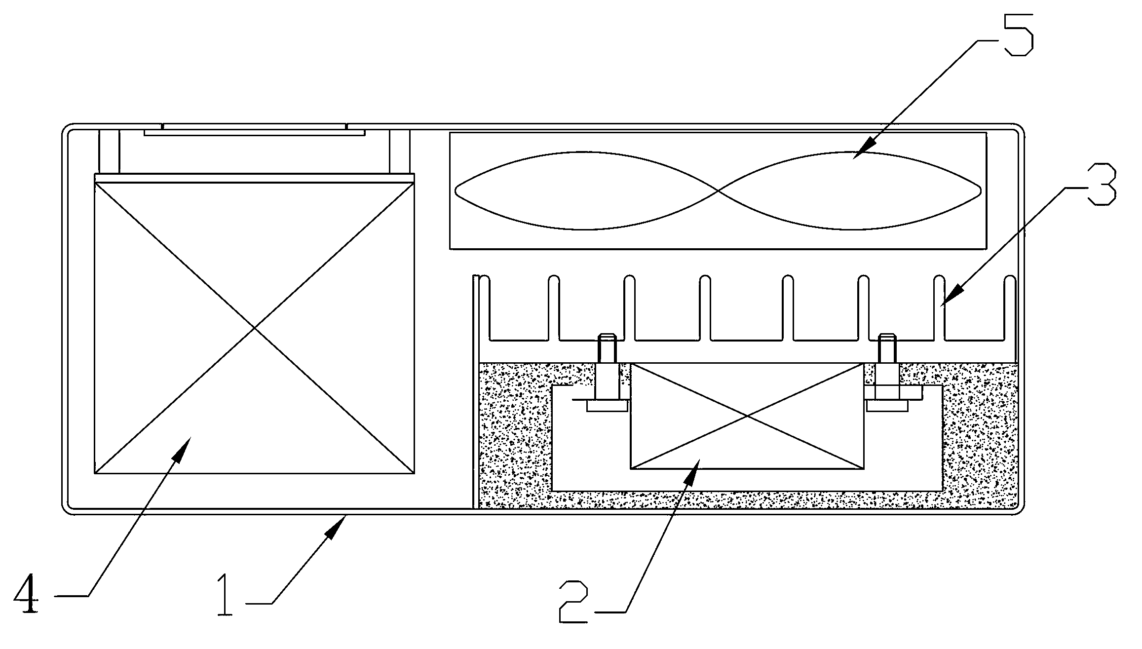
[0018] Such as figure 1 , The electric cabinet dehumidifier of this embodiment includes: a housing 1 , a condensing assembly 2 disposed in the housing 1 , a heater 3 , a control module 4 , a temperature and humidity sensor and a fan 5 .

[0019] The condensing assembly 2 , the heater 3 , the temperature and humidity sensor, and the fan 5 are all connected to the control module 4 .

[0020] The condensing assembly 2 is connected with the heat sink of the heater 3, so that when the heater stops working and the condensing assembly starts cooling, it is convenient to cool the heat sink quickly, so as to expand the condensation surface by the heat sink and facilitate rapid condensation.

[0021] The dehumidification method of the above-mentioned electric cabinet dehumidifier comprises the following steps:

[0022] (1) Heat the air in the electric cabinet to the preset temperature through the heater 3 first, so as to vaporize the condensation in the electric cabinet;

[0023] (2) ...


PUM


Abstract

The invention relates to an electric cabinet dehumidifier comprising a shell, and a condensing assembly, a heater, a control module, a temperature and humidity sensor and a fan which are arranged in the shell, wherein the condensing assembly, the heater, the temperature and humidity sensor and the fan are connected with the control module. The electric cabinet dehumidifier provided by the invention dehumidifies through the cooperation of a heating method and a condensing method so as to completely realize dehumidification and quickly solve the condensation problem, and prevents the secondary condensation problem through automatic control to effectively guarantee the safety problem caused by condensation of the electric equipment.

Description

technical field [0001] The invention relates to the field of dehumidification of electric cabinets in substations, in particular to an electric cabinet dehumidifier and a dehumidification method thereof. Background technique [0002] Substation cabinets include: high-voltage and low-voltage power distribution cabinets, which are used for on-off, control or protection in power system power generation, transmission, distribution, power conversion and consumption. [0003] At present, the dehumidification devices used in domestic electric cabinets are generally heating dehumidification methods, and drainage dehumidification methods are also available, but they have not been promoted yet. [0004] The main principle of heating and dehumidification is that increasing the air temperature can increase the moisture absorption of the air and improve the dryness of the equipment in the box. At this time, the relative humidity in the box is reduced, but the absolute humidity content o...

Claims


Application Information

Patent Timeline
Patent Type & Authority Applications(China)
IPC IPC(8): H02B1/56
CPCH02B1/24H02B1/28H02B1/56H02B1/565
Inventor 王枫史永祥周飚
Owner CHANGZHOU POWER SUPPLY OF JIANGSU ELECTRIC POWER
Why Eureka
Try Eureka