Supercharge Your Innovation With Domain-Expert AI Agents!

Battery charge apparatus for mobilephone

A mobile phone and battery charging technology, applied in battery circuit devices, secondary battery charging/discharging, circuit devices, etc., can solve problems such as damage to circuit parts and batteries, and achieve the effect of preventing overcharging and overheating

Inactive Publication Date: 2013-01-02
HDPRO
View PDF12 Cites 3 Cited by
  • Summary
  • Abstract
  • Description
  • Claims
  • Application Information

AI Technical Summary

Problems solved by technology

[0014] As mentioned above, in the conventional charging device, magnets and / or metal parts are used to make the connection terminals connect when the DC power generated from the charger is applied to the battery mounted on the mobile phone or separated from the mobile phone for charging. They are closely attached to each other, and the magnets and / or metal parts are arranged in a state separated from the connection terminals, so when the magnets and / or metal parts are connected to each other for charging, there is a short circuit caused by contact with the other connection terminals on one side. The problem of causing damage to the circuit part and the battery

Method used


Image

  • Battery charge apparatus for mobilephone
  • Battery charge apparatus for mobilephone
  • Battery charge apparatus for mobilephone

Examples


Embodiment Construction

[0045] Hereinafter, preferred embodiments of the present invention will be described in detail with reference to the accompanying drawings.

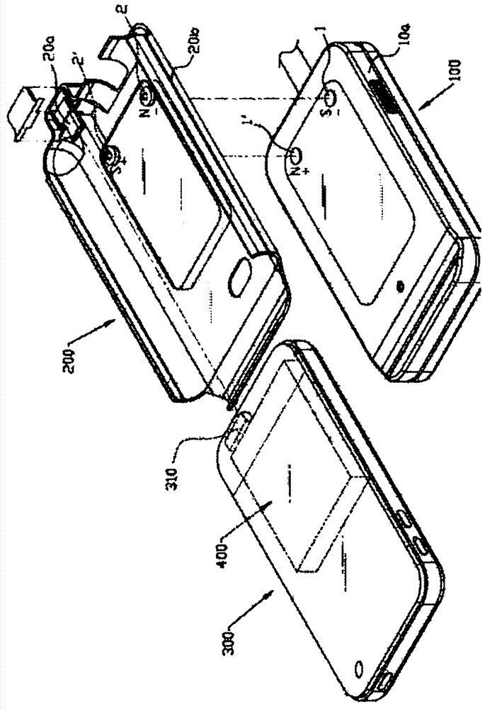
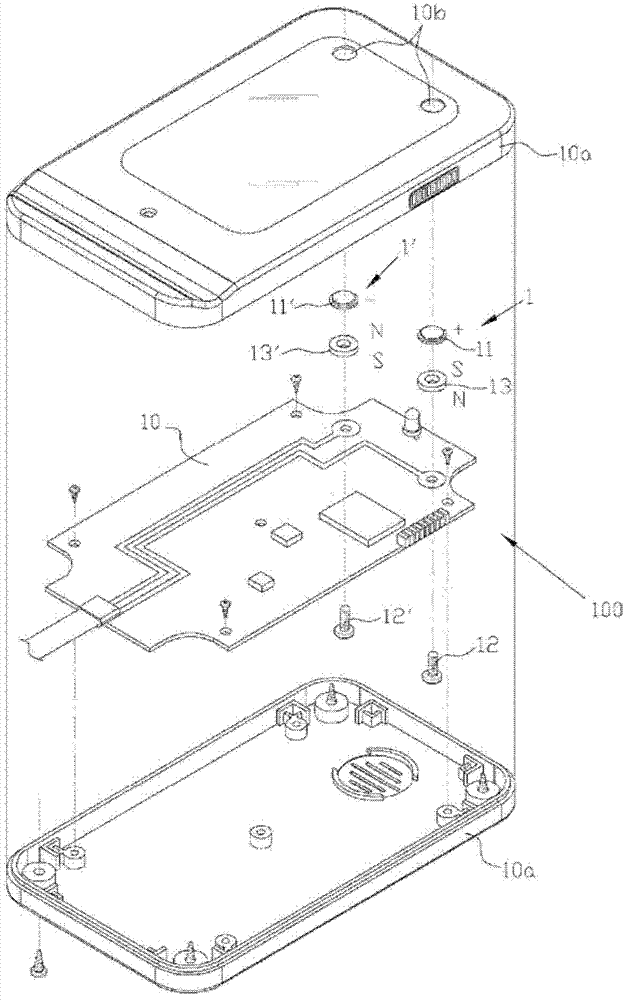
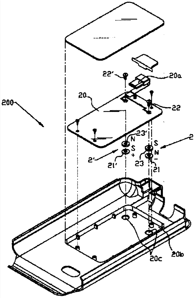
[0046] Figure 1 to Figure 3 It is an exploded perspective view showing a battery charging device for a mobile phone according to the present invention. Reference numeral 100 denotes a charger, 200 denotes a protective cover, 300 denotes a mobile phone, 1, 1' denotes an output contact part, and 2, 2' denotes an input contact part.

[0047] The battery charging device for a portable phone of the present invention includes: a portable phone 300 having a connection jack 310 for connecting current and data; , 1'; and a protective cover 200, which is connected to a data and charging connector (connector) 20a, and is equipped with an input contact part 2, 2' connected to a printed circuit board 20, and the input contact part 2, 2' is connected to the above-mentioned charging The output contact parts 1, 1' of the device 100 are in contact to r...


PUM


Abstract

The battery charge apparatus for a mobile phone proposed by this invention comprises a mobile phone, a charger being configured so as to induce positive electricity and negative electricity from a direct current power source to the output contact portions, an enclosure cover equipped with the PCB-connected input contact portions in such a manner that negative electricity and positive electricity can be supplied by contacting the output contact portions of the charger while being connected to a connector for data link and charging, In this regard, the output contact portions include anode and cathode output terminals which form a couple being exposed through two holes perforated on the top end of a housing thereof, fixation bolts engaged in such a manner that the output terminals are connected to the PCB on the lower part thereof, and the permanent magnets being arranged between the output terminals and the PCB generating magnetic force. Similarly, the input contact portions include anode and cathode output terminals which form a couple being exposed through two holes perforated on the bottom of a base thereof, fixation bolts engaged in such a manner that the input terminals are connected to the PCB on the lower part thereof, and the permanent magnets being arranged in between the input terminals and the PCB generating magnetic force. The output contact portions and the input contact portions are fixed or installed in a manner of moving up and down, and can be mutually contacted and charged through the magnetic force.

Description

technical field [0001] The present invention relates to a battery charging device for a mobile phone, and more specifically to a device for maintaining firm contact between the output and input contact parts of the power supply mounted on the protective cover of the mobile phone and the charger by the magnetic force of a magnet. State, thereby enabling a battery charging device for a portable phone that can be safely charged. Background technique [0002] Generally, a portable mobile terminal (hereinafter referred to as a mobile phone) is a device that transmits and receives data such as voice and image information through the interconnection of a mobile phone, a base station, a mobile phone switching center, and a public switched telephone network. [0003] Such a mobile phone has a built-in rechargeable battery that is charged with a power source for electrically operating various electronic components housed inside and is structurally replaceable to supplement the used po...

Claims


Application Information

Patent Timeline
Patent Type & Authority Applications(China)
IPC IPC(8): H02J7/00
CPCY02E60/12H01M10/46H04M1/04H02J7/0044H02J7/00H04B1/3888Y02E60/10H01M10/44
Inventor 高润和
Owner HDPRO
Features
  • R&D
  • Intellectual Property
  • Life Sciences
  • Materials
  • Tech Scout
  • Unparalleled Data Quality
  • Higher Quality Content
  • 60% Fewer Hallucinations
Learn More