

Tomogram observation apparatus, processing method, and non-transitory computer-readable storage medium
A technology of tomographic image and equipment, applied in the field of tomographic image observation equipment
- Summary
- Abstract
- Description
- Claims
- Application Information
AI Technical Summary
Problems solved by technology
Method used
Image

Examples
no. 1 example
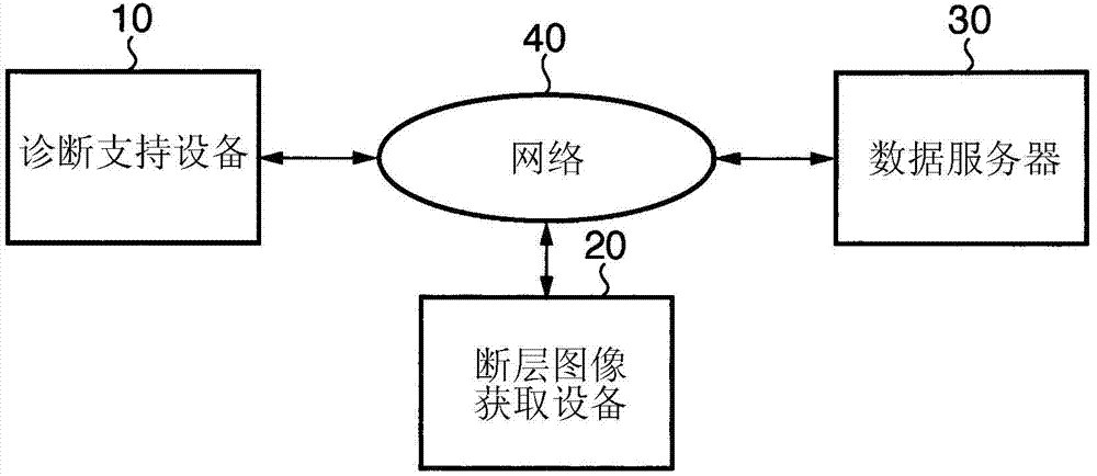
[0025] figure 1 is a diagram showing an example of the overall configuration of the diagnosis support system according to the embodiment of the present invention. Note that this example will exemplify diagnostic support for follow-up observation of glaucoma.
[0026] In this diagnosis support system, a diagnosis support device 10, a tomographic image acquisition device 20, and a data server 30 are connected to each other via a network 40 constituted by a LAN (Local Area Network) or the like. Note that the devices need not always be connected to each other via the network 40 as long as the devices can communicate with each other. For example, these devices may be connected to each other via USB (Universal Serial Bus), IEEE1394, or the like, or may be connected to each other via WAN (Wide Area Network).
[0027] In this case, the tomographic image acquisition device 20 is realized by time domain OCT or Fourier domain OCT, and has a function of obtaining a tomographic image sho...
no. 2 example
[0085]Next, a second embodiment will be described. The first embodiment has exemplified the case where images of the same subject's eye captured at different times are compared at the time of follow-up observation. For comparison, the second embodiment will exemplify a case where the left eye and the right eye of the same subject are compared with each other. This is because the left and right eyes of the same subject exhibit little deviation in the size of the optic nerve head. It is known that the size of the optic nerve head varies greatly among individuals. As a comparison, the left and right eyes of the same person show little deviation in the size of the optic nerve head (it is reported that the size difference between the left and right nipples of 99% of people falls within 1mm~2mm).
[0086] In this case, the second embodiment correlates tomographic images with each other paying attention to the shape of the nipple boundary. The second embodiment differs from the fi...
no. 3 example
[0093] Next, a third embodiment will be described. The third embodiment will exemplify a case where tomographic images to be compared are processed to clarify differences between these tomographic images and present the differences to an operator. More specifically, when displaying tomographic images to be compared, the apparatus performs difference processing to display the difference between the two tomographic images to the operator. The difference between this embodiment and the first embodiment and the second embodiment is that Figure 4 The display control processing shown in step S107. Since the device configuration and processing other than this display control processing are the same as those of the first embodiment and the second embodiment, descriptions for both will be omitted.
[0094] In this case, for example, the difference image may be generated by subtracting the luminance value of the corresponding pixel of the second tomographic image from the luminance v...
PUM
 Abstract
Description
Claims
Application Information