

Electrostatic Atomization Device
An electrostatic atomization, dielectric technology, applied in electrostatic heating/cooling devices, spray discharge devices, spray devices, etc., can solve the problem of difficulty in ensuring the amount of water generated by charged particles
- Summary
- Abstract
- Description
- Claims
- Application Information
AI Technical Summary
Problems solved by technology
Method used
Image

Examples
no. 1 example
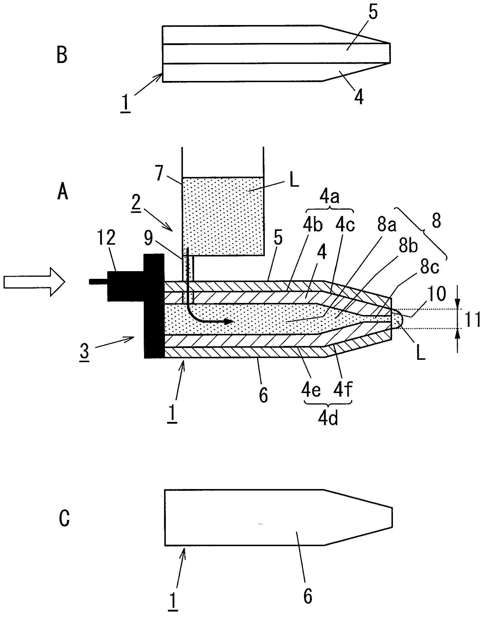
[0026] figure 1 The basic structure of the electrostatic atomization device according to the first embodiment of the present invention is schematically shown. The electrostatic atomization device of the present embodiment is configured to apply a voltage (microwave electric field) to the liquid L held by the atomization unit 1 , thereby generating charged fine particle water based on the liquid L. The electrostatic atomization device of the present embodiment includes: a liquid supply part 2 for supplying the liquid L to the atomization unit 1; Voltage (microwave electric field).
[0027] The atomization unit 1 includes a microstrip line with a first end and a second end. Typically, a microstrip line consists of a dielectric body, which has a first side and a second side; a strip conductor, which is in contact with the first side of the dielectric body; and a ground plane conductor, which is connected to the second side of the dielectric body. The two sides are in contact. ...
no. 2 example
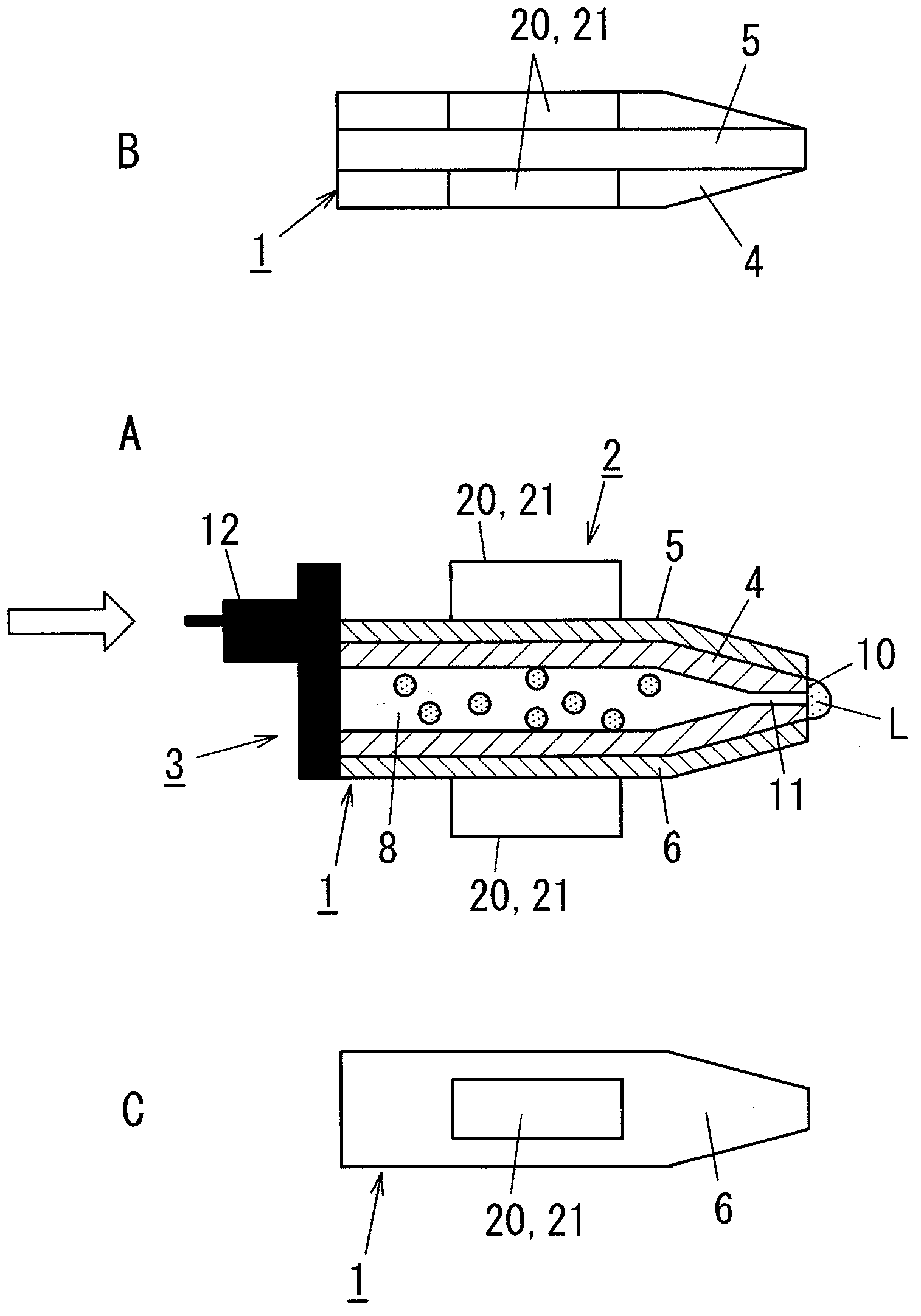
[0034] Next, refer to figure 2 An electrostatic atomization device according to a second embodiment of the present invention will be described. The basic structure of this example is the same as that of the first embodiment, so only the characteristic structure of this embodiment will be described in detail, and the same structure as the first embodiment will not be described in detail.
[0035] The electrostatic atomizing device of the present embodiment is provided with a cooling unit 20 as the liquid supply part 2 for supplying the liquid L up to the front end side of the atomizing unit 1 (that is, the concentrated area of the microwave electric field), wherein the cooling unit 20 is used to The cylindrical or hollow dielectric body 4 constituting the atomization unit 1 is cooled. The cooling unit 20 includes a Peltier unit 21 whose heat-absorbing side is the side connected to the dielectric body 4, and is configured to cool the cylindrical or hollow dielectric body 4 i...
no. 3 example
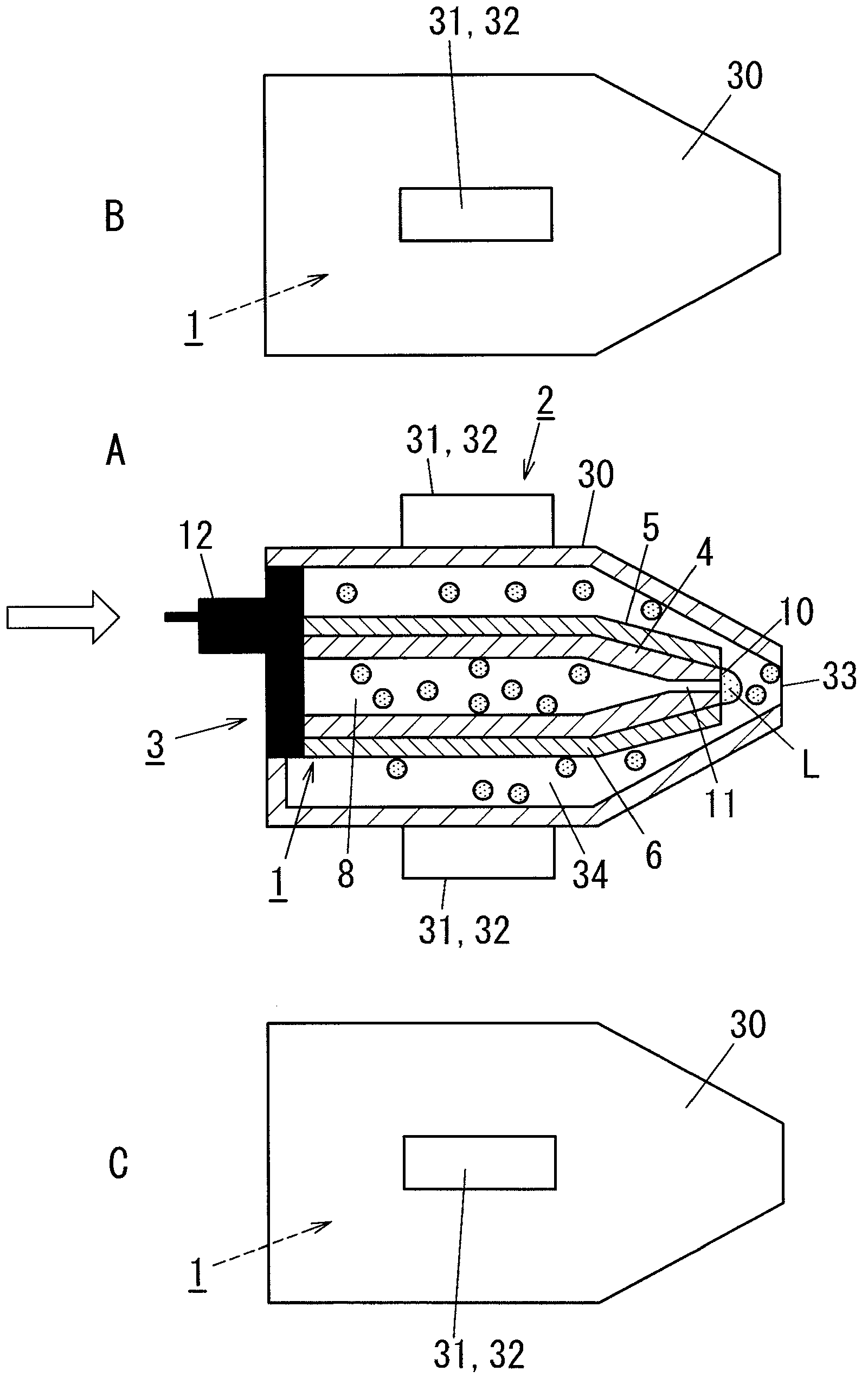
[0040] Next, refer to image 3 An electrostatic atomization device according to a third embodiment of the present invention will be described. The basic structure of this embodiment is the same as that of the first embodiment and the second embodiment, so only the characteristic structure of this embodiment will be described in detail and the same structure as the first embodiment and the second embodiment will not be described in detail.
[0041] As the liquid supply member 2 for supplying the liquid L up to the front end side of the atomizing unit 1 (that is, the concentrated area of the microwave electric field), the electrostatic atomizing device of the present embodiment is configured with: a cylindrical or hollow atomizing unit A case 30 configured to surround the atomization unit 1 ; and a cooling unit 31 for cooling the atomization unit case 30 . The atomizing unit case 30 is made of a material with high thermal conductivity. The cooling unit 31 includes a Peltier ...
PUM
 Abstract
Description
Claims
Application Information