Battery having a cooling plate and motor vehicle having a corresponding battery

A technology for motor vehicles and cooling plates, which is applied in battery/battery traction, electric vehicles, vehicle energy storage, etc. It can solve the problem that the battery module cannot be fixed in advance, achieve small thermal contact resistance, realize heat export, and simplify installation The effect of the process

Active Publication Date: 2013-01-02
ROBERT BOSCH GMBH +1
View PDF6 Cites 7 Cited by
  • Summary
  • Abstract
  • Description
  • Claims
  • Application Information

AI Technical Summary

Problems solved by technology

Although several battery cells are positioned relative to each other, the fastening of the battery modules to the cooling plate cannot be preset

Method used


Image

  • Battery having a cooling plate and motor vehicle having a corresponding battery

Examples


Embodiment Construction

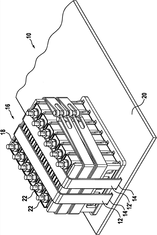
[0020] exist figure 1 An example of a cooling plate 10 according to the invention is shown in . This cooling plate has an upper side 20 . Here, two fixing straps are arranged on the cooling plate 10, a first fixing strap 12 and a second fixing strap 12'. The battery modules 16 are fastened on the top side 20 of the cooling plate 10 by means of said fastening straps 12, 12'. The battery module 16 preferably consists of a plurality of battery cells 18 arranged in series. The bottom side of the battery module 16 is preferably designed in such a way that the bottom side of the battery module 16 lies flat against the top side 20 of the cooling plate 10 .

[0021] The cooling plate 10 serves to regulate the temperature of at least one battery module 16 . For this reason, the cooling plate 10 is preferably made of metal, since metal has a high thermal conductivity. After assembly, the battery modules 16 are directly in contact with the cooling plate 10 . Preferably, the bottom ...


PUM


Abstract

The invention relates to a battery which has at least one battery module (16) having a lower face, a cooling plate (10) having an upper face (20) and a fixing system for the at least one battery module (16), which is arranged on the upper face (20) of the cooling plate (10) and connected to the cooling plate (10). The fixing system has at least one fixing strap (12, 12'). By means of the at least one fixing strap (12, 12'), the at least one battery module (16) is fixed on the cooling plate (10) in such a way that the lower face of the battery module (16) is in direct contact with the upper face (20) of the cooling plate (10). The invention further relates to a motor vehicle having said battery.

Description

technical field [0001] The invention relates to a battery with a cooling plate and to a motor vehicle with the battery, wherein the design of the fastening system allows particularly efficient assembly and cooling of the battery. Background technique [0002] It is known to arrange a battery module with its bottom side on the top side of a cooling plate. In this case, holes are arranged in the cooling plate and the battery modules are connected to the cooling plate by means of screw connections. The disadvantage here is that the screw connection has to be applied from the underside of the cooling plate, which complicates the assembly process. Furthermore, during screwing in, a defined pressing force of the battery module on the cooling plate is achieved relatively cost-effectively only by obtaining the resistance torque of the screw. The contact force should be of a defined magnitude in order to keep the thermal contact resistance between the battery modules and the coolin...

Claims


Application Information

Patent Timeline
Patent Type & Authority Applications(China)
IPC IPC(8): H01M10/50B60L50/64
CPCY02E60/12H01M2/10H01M10/5004H01M10/5016H01M10/5053H01M10/625H01M10/6554H01M10/613Y02E60/10H01M50/249B60L50/64H01M50/209Y02T10/70
Inventor B·根德林M·迪尔R·安格鲍尔C·布贝克A·吕勒
Owner ROBERT BOSCH GMBH
Why Eureka
Try Eureka