The rotating shaft of the spindle under the twisting machine

An all-in-one machine, rotating shaft technology, applied in spinning machines, continuously wound spinning machines, textiles and papermaking, etc., can solve problems such as easy deformation, friction at joints, easy deformation, etc., to prevent bending Deformation, Deformation Prevention Effect

Inactive Publication Date: 2015-12-30
宜宾长信线业有限责任公司
View PDF11 Cites 0 Cited by
  • Summary
  • Abstract
  • Description
  • Claims
  • Application Information

AI Technical Summary

Problems solved by technology

[0002] At present, the rotating shaft in the twisting machine is only suitable for the production of various thread products on the plastic bobbin, mainly after the spun yarn is twisted into strands and wound on the plastic bobbin, but the following defects still exist in this method: 1. Since the twisted yarn is wound on the plastic bobbin, it will be sold together with the plastic bobbin when the yarn is sold, and the unit price of the plastic bobbin is relatively high, which increases the production cost accordingly; The yarn on the plastic bobbin is sold after being formed into a bobbin or twisted into a final product. Due to the complicated production process, the production cost is further increased; 3. Since the plastic bobbin is a non-degradable material, it is easy to pollute the environment, so it is It is necessary to use a degradable bobbin (such as a paper tube) to wind the yarn, but due to the low strength of the paper tube and easy deformation, the quality of the product will be poor or even impossible to produce
This patent also has the following deficiencies in actual use: 1. In this patent, the high-speed rotation of the spindle drives the support to generate centrifugal force to tighten the bobbin. The centrifugal force generated by the supporter is small, which is easy to shake the bobbin and affect the product quality. When the bobbin and the supporter are used for a long time, there will be gaps at the joint due to friction, and the bobbin may be shaken during operation. Break away from the spindle rod, thereby causing equipment damage; 2. The spindle rod cannot use easily degradable materials such as paper tubes as the bobbin to wind the yarn, the production cost is high, and it is easy to pollute the environment
Although this patent can use the paper tube to wind the yarn, it still has the following deficiencies in actual use: 1. This patent mainly fixes the paper tube through the rubber ring on the flange ring in the middle, but due to the strength of the paper tube Low, easy to deform, and the rubber ring is soft and can only support the middle of the paper tube, which will cause the center of gravity of the paper tube to be unstable, the effect of fixing the paper tube is not good, and affect the product quality; If the amount of thread wound below 500g, the amount of yarn wound on each paper tube is small, the production cost is high, and if the amount of yarn wound on each paper tube is increased, the spindle or support will be damaged due to the load Three, the support body is mainly used on the winding machine, because the speed of the winding machine is 2000 rpm, while the speed of the twisting machine is as high as 6500 rpm, which is much higher than the speed of the winding machine , therefore, applying this structure to the twisting machine will cause the paper tube to swing greatly, making it impossible to wind the wire onto the bobbin

Method used


Image

  • The rotating shaft of the spindle under the twisting machine

Examples


Embodiment Construction

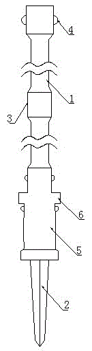
[0035]A rotating shaft of a lower spindle of an integrated twisting machine, including a bobbin support column 1, at least three annular flanges 3 with the same outer diameter are arranged on the bobbin support column 1, three annular flanges 3 They are respectively arranged on the upper, middle and lower parts of the bobbin supporting column 1, and the upper annular flange 3 and the lower annular flange 3 are respectively provided with at least three retractable supporters for supporting the bobbin.

[0036] Further, the rotating shaft is preferably configured as a cylinder, and may also be configured as a cone or a truncated cone.

[0037] Further, the outer diameter of the annular flange 3 is 29-30mm, the width is 24-26mm, the outer diameter of the annular flange 3 can be 29mm or 30mm, preferably the outer diameter of the annular flange 3 is 29.5mm, the annular The width of flange 3 can be 24mm, also can be 26mm, preferably its width is 25mm; The distance between described ...


PUM

PropertyMeasurementUnit
lengthaaaaaaaaaa
widthaaaaaaaaaa
diameteraaaaaaaaaa

Abstract

The invention discloses a rotating shaft of a low spindle of a yarn twisting and cone winding integrated machine. The rotating shaft comprises a winding tube support column, wherein three annular flanges with same outer diameters are at least arranged on the winding tube support column and are respectively arranged on the upper part, the middle part and the lower part of the winding tube support column, and the upper annular flange and the lower annular flange are respectively provided with at least three telescopic holders for supporting a winding tube. After the rotating shaft is adopted, the winding tube made of an easily degradable material is used for replacing a plastic bobbin for winding yarns, 1Kg of yarns can be wound on each winding tube, and the convenience is brought for collecting the winding tubes from the spindle.

Description

technical field [0001] The invention relates to the technical field of textile machinery, in particular to a rotating shaft of a lower spindle of an integrated twisting and barrel forming machine. Background technique [0002] At present, the rotating shaft in the twisting machine is only suitable for the production of various thread products on the plastic bobbin, mainly after the spun yarn is twisted into strands and wound on the plastic bobbin, but the following defects still exist in this method: 1. Since the twisted yarn is wound on the plastic bobbin, it will be sold together with the plastic bobbin when the yarn is sold, and the unit price of the plastic bobbin is relatively high, which increases the production cost accordingly; The yarn on the plastic bobbin is sold after being formed into a bobbin or twisted into a final product. Due to the complicated production process, the production cost is further increased; 3. Since the plastic bobbin is a non-degradable mater...

Claims


Application Information

Patent Timeline
Patent Type & Authority Patents(China)
IPC IPC(8): D01H1/24D01H7/16D01H7/10D01H1/36
Inventor 杨书磊杨学利刘涛
Owner 宜宾长信线业有限责任公司
Why Eureka
Try Eureka