
Vibration damping device, vibration damping equipment and vibration damping system

A technology of vibration-damping equipment and vibration-damping devices, which is applied in the direction of shock absorbers, hoisting devices, mechanical equipment, etc., can solve problems such as long damping time of shock absorbers, achieve short vibration-damping time, large bearing capacity, reduce vibration The effect of oscillation time

Active Publication Date: 2014-11-12
SHANGHAI MICRO ELECTRONICS EQUIP (GRP) CO LTD
View PDF8 Cites 0 Cited by
  • Summary
  • Abstract
  • Description
  • Claims
  • Application Information

AI Technical Summary

Problems solved by technology

[0005] The object of the present invention is to provide a vibration damping device, vibration damping equipment and vibration damping system, to solve the problem of long damping time of existing shock absorbers

Method used


Image

  • Vibration damping device, vibration damping equipment and vibration damping system
  • Vibration damping device, vibration damping equipment and vibration damping system
  • Vibration damping device, vibration damping equipment and vibration damping system

Examples


Embodiment 1

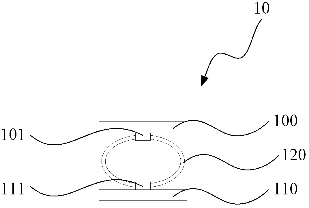
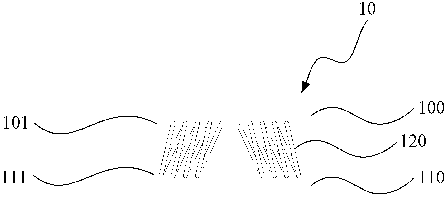
[0030] Please refer to Figure 1a and Figure 1b ,in, Figure 1a It is the front view of the damping device of Embodiment 1 of the present invention; Figure 1b It is a side view of the vibration damping device of Embodiment 1 of the present invention.

[0031] Such as Figure 1a and Figure 1b As shown, the damping device 10 includes: an upper support plate 100; a lower support plate 110, the lower support plate 110 is parallel to the upper support plate 100; a plurality of metal rings 120, the plurality of metal rings 120 are connected to the An upper support plate 100 and a lower support plate 110 .

[0032] In the vibration damping device 10 provided in this embodiment, the vibration is damped by connecting the metal ring 120 of the upper support plate 100 and the lower support plate 110. Since the inherent elasticity of the metal ring 120 is used, there is no need to carry out the vibration between the metal rings 120. Energy transfer, i.e. no need for long-distance en...

Embodiment 2

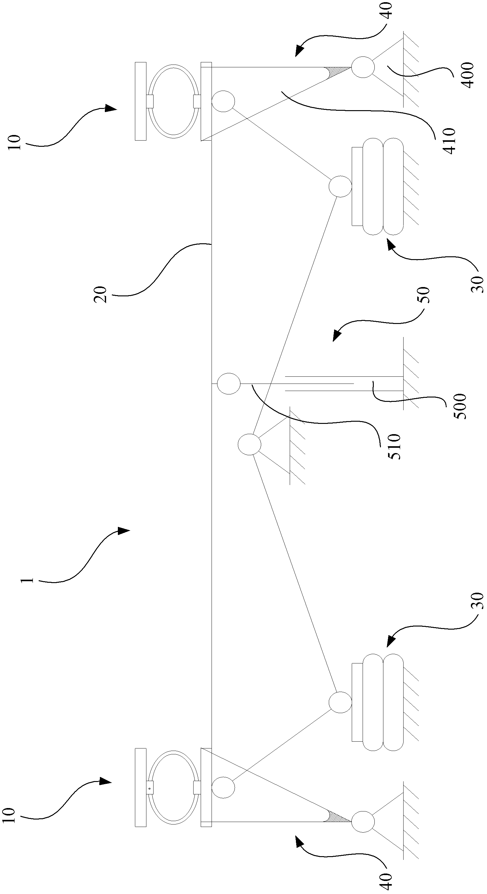
[0038] Please refer to figure 2 , which is a schematic diagram of the vibration damping device in Embodiment 2 of the present invention. Such as figure 2 As shown, the damping device 1 includes: a damping device 10; a connecting plate 20, the damping device 10 is fixed on the connecting plate 20; a lifting airbag 30, the lifting airbag 30 is connected with the connecting plate 20, Used to change the height of the connecting plate 20 ; a locking device 40 , the locking device 40 is movably connected with the connecting plate 20 to support the connecting plate 20 .

[0039] The vibration damping device 1 includes a vibration damping device 10, so that it can also achieve beneficial effects such as short vibration damping time, large bearing capacity, and long service life. In addition, the lifting airbag 30 of the vibration-damping device 1 facilitates loading and unloading of loads on the vibration-damping device 1 .

[0040] In this embodiment, there are two damping devic...


PUM


Abstract

The invention provides a vibration damping device, vibration damping equipment and a vibration damping system. The vibration damping device comprises an upper supporting plate, a lower supporting plate and a plurality of metal rings, wherein the lower supporting plate is parallel to the upper supporting plate; and the plurality of metal rings are connected with the upper supporting plate and the lower supporting plate. The vibration damping equipment comprises the vibration damping device, a connecting plate, a lifting air bag and a locking device, wherein the vibration damping device is fixed on the connecting plate; the lifting air bag is connected with the connecting plate and used for changing the height of the connecting plate; the locking device is connected with the connecting plate movably and used for supporting the connecting plate. The vibration damping system comprises a plurality of vibration damping equipment which is connected through fixed devices. The vibration damping device, the vibration damping equipment and the vibration damping system can shorten the vibration damping time and improve the vibration damping effect.

Description

technical field [0001] The invention relates to a vibration damping device, a vibration damping device and a vibration damping system. Background technique [0002] Transportation is an indispensable operation in the production and life of modern society, which realizes the change of the spatial position of people and objects. For ordinary cargo transportation, it also needs to consider multiple issues, such as: the preservation of the value of the transported goods, and the prevention of damages such as rain, damp, flooding, rust, damage, and loss that may occur during the process; Saving of operating resources, reducing packaging resources, management resources, etc. [0003] For precision mechanical equipment, vibration reduction needs to be considered during transportation. For example, some precision mechanical equipment in the field of microelectronics not only has high precision and is very expensive, but also has a relatively heavy quality. Therefore, there are str...

Claims


Application Information

Patent Timeline
Patent Type & Authority Patents(China)
IPC IPC(8): F16F7/00F16F15/06B66F3/35B66F7/16
Inventor 宋兴龙
Owner SHANGHAI MICRO ELECTRONICS EQUIP (GRP) CO LTD
Learn More