Phase retrieval based 4f mirror surface detection imaging system and phase retrieval based 4f mirror surface detection imaging method

A technology of phase recovery and imaging method, applied in the field of image processing, can solve the problems of not getting rid of, affecting the measurement accuracy, not using the light wave sparsity at the measured mirror surface, etc., to improve the accuracy, overcome low accuracy, good stability and easy. operational effects

Inactive Publication Date: 2013-01-09
XIDIAN UNIV
View PDF4 Cites 24 Cited by
  • Summary
  • Abstract
  • Description
  • Claims
  • Application Information

AI Technical Summary

Problems solved by technology

This method is mainly aimed at detection devices and methods with large mirrors and large error ranges. There are two deficiencies in this patent: First, it still does not get rid of moving the CCD camera to collect multiple light intensity images of the light waves at the mirrors to be tested. The first method is to construct the phase of the light wave at the measured mirror surface, and finally detect the surface error of the mirror surface; the second is that the intensity and phase of the light wave at the measured mirror surface are not used when reconstructing the phase of the light wave at the measured mirror surface using the phase recovery algorithm of step-by-step filtering. sparsity, which will inevitably reduce the robustness of the reconstructed phase to environmental noise, thus affecting the final measurement accuracy

Method used


Image

  • Phase retrieval based 4f mirror surface detection imaging system and phase retrieval based 4f mirror surface detection imaging method
  • Phase retrieval based 4f mirror surface detection imaging system and phase retrieval based 4f mirror surface detection imaging method
  • Phase retrieval based 4f mirror surface detection imaging system and phase retrieval based 4f mirror surface detection imaging method

Examples


Embodiment Construction

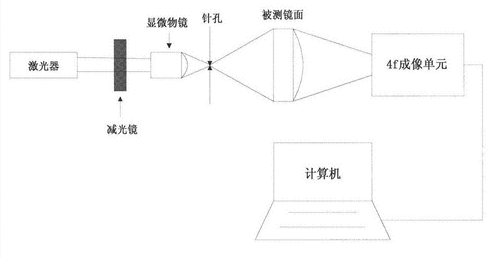
[0033] Attached below figure 1 , to further describe the system of the present invention.

[0034] The 4f mirror detection and imaging system based on phase recovery of the present invention includes a laser, a light reduction mirror, a microscope objective lens, a pinhole, a measured mirror, a 4f imaging unit, and a computer.

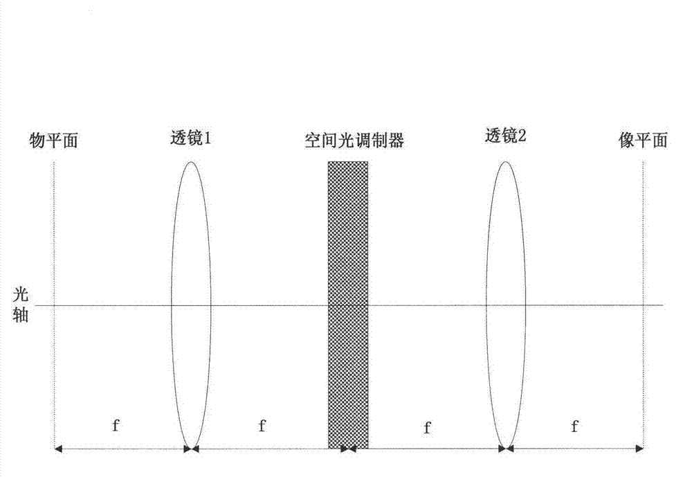
[0035] Refer to attached figure 2 , The 4f imaging unit includes a lens 1, a spatial light modulator, a lens 2, and a CCD camera.

[0036] The laser is set in parallel behind the light reducing mirror. The light emitted by the laser is modulated by the light reducing mirror to avoid the oversaturation of the CCD camera. The microscopic objective lens is located in the direction parallel to the light reducing mirror, and the pinhole is placed parallel to the focal length of the microscopic objective lens. At , the center of the laser, light reducing mirror, microscope objective lens and pinhole are placed on the same straight line. The mirror to be ...


PUM


Abstract

The invention discloses a phase retrieval based 4f mirror surface detection imaging system and a phase retrieval based 4f mirror surface detection imaging method. The system comprises a laser, a neutral density filter, a microobjective, a pinhole, a measured mirror surface, a 4f imaging unit and a computer, wherein the 4f imaging unit comprises a lens 1, a space light modulator, a lens 2 and a charge coupled device (CCD) camera. The light emitted by the laser irradiates the measured mirror surface after passing through the neutral density filter, the microobjective and the pinhole. The CCD camera arranged in the 4f imaging unit is used for acquiring a plurality of times of a light wave modulation image, and then the image is sent into the computer for sparse constraint phase recovery treatment. Based on the acquired light wave intensity image of the measured mirror surface, the method utilizes the sparse constraint phase recovery treatment to obtain the phase position of the light wave on the measured mirror surface, thus realizing the error detection for the measured mirror surface. The invention has the advantages of being high in accuracy, good in stability, simple in operation and good in noise robustness.

Description

technical field [0001] The invention belongs to the technical field of image processing, and further relates to a phase recovery-based 4f mirror detection imaging system and a method thereof in the technical field of optical measurement and image processing. The invention is based on the optical spatial light modulation 4f imaging system and the phase recovery algorithm to jointly detect the mirror surface error, and can realize the error detection of the optical mirror surface after performing optical imaging on the measured mirror surface. Background technique [0002] As various optical mirrors have been used more and more widely in the fields of space optics, aviation and military. At present, the existing image measurement technology and optical mirror detection technology based on light wave diffraction and Fourier optics are mainly based on the principle of light diffraction. The relevant principle uses a certain phase recovery optimization algorithm to realize the d...

Claims


Application Information

Patent Timeline
Patent Type & Authority Applications(China)
IPC IPC(8): G01B11/24G01M11/02
Inventor 石光明刘阳刘丹华高大化王立志李国
Owner XIDIAN UNIV
Why Eureka
Try Eureka