Device for detecting oscillating quantity of adjusting gear of counter

A detection device and counter technology, which is applied to measurement devices, mechanical measurement devices, testing/calibration devices, etc., can solve problems such as affecting gear transmission, increase in gear transmission friction, poor measurement stability of gas meters, etc., and achieve improved stability. , to ensure a balanced, easy-to-promote effect

Inactive Publication Date: 2013-01-09
CHENGDU QINCHUAN IOT TECH CO LTD
View PDF5 Cites 4 Cited by
  • Summary
  • Abstract
  • Description
  • Claims
  • Application Information

AI Technical Summary

Problems solved by technology

[0002] At present, the adjustment teeth in the mechanical counter of the gas meter generally have vertical and horizontal swings in the actual use process, which affects the gear transmission, resulting in poor measurement stability of the gas meter.
The maximum difference between the multiple measurement errors of each flow point of the gas meter exceeds the range specified by the national standard. The main reason is that the swing of the counter adjustment teeth is too large, and the swing of the counter adjustment teeth will also increase the friction force during gear transmission. Large, resulting in the instability of the gear transmission of the gas meter and reducing the service life of the gas meter
Although all kinds of smart gas meters currently use electronic forms such as single-chip microcomputers to count and display on LCD screens, membrane gas meters using mechanical counters are still one of the mainstream gas meters used on a large scale at present. Therefore, how to detect mechanical The longitudinal and lateral swings of the adjusting teeth of the counter before delivery or assembly are still a difficult problem for gas meter manufacturers, and it is necessary to conduct further research on it

Method used


Image

  • Device for detecting oscillating quantity of adjusting gear of counter
  • Device for detecting oscillating quantity of adjusting gear of counter

Examples


Embodiment Construction

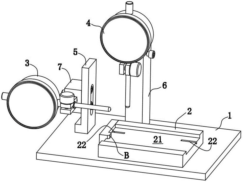
[0017] First of all, I will explain the "diameter indicator" repeatedly mentioned in the present invention. The indicator is a kind of measuring tool. Its English translation is Dial Indicators. It is a universal length measuring tool made of precision rack and pinion mechanism. It is usually composed of measuring head, measuring rod, shockproof spring, rack, pinion, hairspring, round dial and pointer. The dial indicator was made by B.C. Ames in the United States in 1890. It is often used for length measurement of shape and position errors and small displacements. At present, the dial of the commonly used dial indicator is printed with 100 equal division scales, that is, each division value is equivalent to the movement of the measuring rod by 0.01 mm. If there are 1000 equal division scales printed on the round dial, each division value is 0.001 mm, and this measuring tool is called a dial indicator. Change the shape of the probe and equip it with the corresponding bracket t...


PUM


Abstract

The invention discloses a device for detecting an oscillating quantity of an adjusting gear of a counter, belonging to an instrument detection device. The detecting device comprises a base plate, and at least a first support frame and a second support frame, wherein the at least two support frames are arranged on the base plate; the base plate is also provided with a counter fixed platform; the at least two support frames are respectively provided with a first dial indicator and a second dial indicator; the first dial indicator is transversely arranged on the first support frame while the second dial indicator is lengthways arranged on the second support frame; and the line from the side head of the second dial indicator to the base plate is contacted with the counter fixed platform. The device for detecting the oscillating quantity of the adjusting gear of the counter, provided by the invention, has a simple structure, can be used for detecting horizontal and vertical oscillating quantities of counters of various types at the same time by utilizing the detection principle of the dial indicator, is particularly suitable for detecting the horizontal and vertical oscillating quantities of gas meters, and is easy to popularize.

Description

Technical field [0001] The present invention relates to an instrument detection device. More specifically, the present invention mainly relates to a detection device for the swing amount of a counter adjusting tooth. Background technique [0002] At present, the regulating teeth in the mechanical counter of the gas meter generally swing in both vertical and horizontal directions during actual use, which affects the gear transmission, resulting in poor metering stability of the gas meter. The maximum difference between the multiple measurement errors at each flow point of the gas meter exceeds the range specified by the national standard. The main reason is that the counter adjustment tooth swing is too large, and the counter adjustment tooth swing will also increase the friction during gear transmission. Large, cause the instability of the gas meter gear transmission and reduce the service life of the gas meter. Although all types of smart gas meters use electronic forms such as...

Claims


Application Information

Patent Timeline
Patent Type & Authority Applications(China)
IPC IPC(8): G01F25/00G01B5/00
Inventor 邵泽华吴岳飞熊建宏
Owner CHENGDU QINCHUAN IOT TECH CO LTD
Why Eureka
Try Eureka