
Control loop design method capable of reflecting vibration attenuation system performance

A vibration reduction system and control loop technology, which is applied in general control systems, control/regulation systems, instruments, etc., can solve problems such as the complexity of the simulation model establishment process, and achieve the effect of simplifying the simulation model

Active Publication Date: 2013-01-09
INST OF OPTICS & ELECTRONICS - CHINESE ACAD OF SCI
View PDF8 Cites 0 Cited by
  • Summary
  • Abstract
  • Description
  • Claims
  • Application Information

AI Technical Summary

Problems solved by technology

At present, the simulation system is mainly carried out in MATLAB. The control loop is established in the Simulink module, and the vibration reduction system model is established in the SimMechanics module. Generally speaking, the establishment process of the simulation model is relatively complicated; There is no relevant report on the hardware-in-the-loop simulation of the photoelectric tracking system on the vibration system platform

Method used


Image

  • Control loop design method capable of reflecting vibration attenuation system performance
  • Control loop design method capable of reflecting vibration attenuation system performance
  • Control loop design method capable of reflecting vibration attenuation system performance

Examples


Embodiment Construction

[0020] The present invention will be described in detail below in combination with specific embodiments.

[0021] The method of the present invention takes the azimuth system as an example (the method of the pitch system is the same as that of the azimuth system), and the specific implementation is as follows:

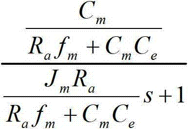
[0022] (1) Measure or calculate the moment of inertia J of the azimuth system of the photoelectric tracking system m , The viscous friction coefficient f of the motor and the load converted to the motor shaft m .

[0023] In the ground-based photoelectric tracking system, the controlled objects of the control system are:

[0024] C m R a f m + C m C e J...


PUM


Abstract

The invention discloses a control loop design method capable of reflecting vibration attenuation system performance, which is suitable for simulation or semi-physical simulation of a control system of a photoelectric tracking system or a radar system which is arranged on a vibration attenuation system. Aiming at the situations that the vibration attenuation system and the control system are established relatively independently during simulation and the photoelectric tracking system is required to be fixed on a physical platform during testing, a three-order system is used as a controlled object in a control loop, and the influence of the vibration attenuation system on the control loop of the photoelectric tracking system is reflected. An implement method comprises the following steps of: substituting the original one-order system by the three-order system containing the vibration attenuation system to serve as the controlled object so as to design the control loop. The design can be realized in the control loop of a simulation or actual system.

Description

technical field [0001] The invention relates to a control loop design method that can reflect the performance of the vibration reduction system. Specifically, it is aimed at the relatively independent establishment of the vibration reduction system and the control system during simulation, and the photoelectric tracking system needs to be fixed on the physical model of the vibration reduction system during the test. To solve the problem, realize the performance of the vibration reduction system in the control system, and realize the semi-physical simulation of the photoelectric tracking system installed on the vibration reduction system platform on the ground-based photoelectric tracking system. Background technique [0002] In order to improve the mobility of the photoelectric tracking system, it is necessary to install the photoelectric tracking system on the moving platform to work. At the same time, in order to ensure the safety and reliability of the photoelectric tracki...

Claims


Application Information

Patent Timeline
Patent Type & Authority Applications(China)
IPC IPC(8): G05B17/02
Inventor 刘兴法杜俊峰扈宏毅包启亮
Owner INST OF OPTICS & ELECTRONICS - CHINESE ACAD OF SCI
Learn More