Magnetic insensitive latch actuated relay for electricity meter

A relay and latch technology, applied in electromagnetic relays, electromagnetic relay details, relays, etc., can solve problems such as current short-term pulse waveform interference, operation interference, electromagnetic relay influence, etc., to avoid magnetic field interference.

Inactive Publication Date: 2013-01-09
KAMSTRUP
View PDF1 Cites 11 Cited by
  • Summary
  • Abstract
  • Description
  • Claims
  • Application Information

AI Technical Summary

Problems solved by technology

However, the electromagnetic relay may be affected by the external magnetic field, and the operation will be disturbed
Furthermore, the electromagnetic forces operating on t

Method used


Image

  • Magnetic insensitive latch actuated relay for electricity meter
  • Magnetic insensitive latch actuated relay for electricity meter
  • Magnetic insensitive latch actuated relay for electricity meter

Examples


Embodiment Construction

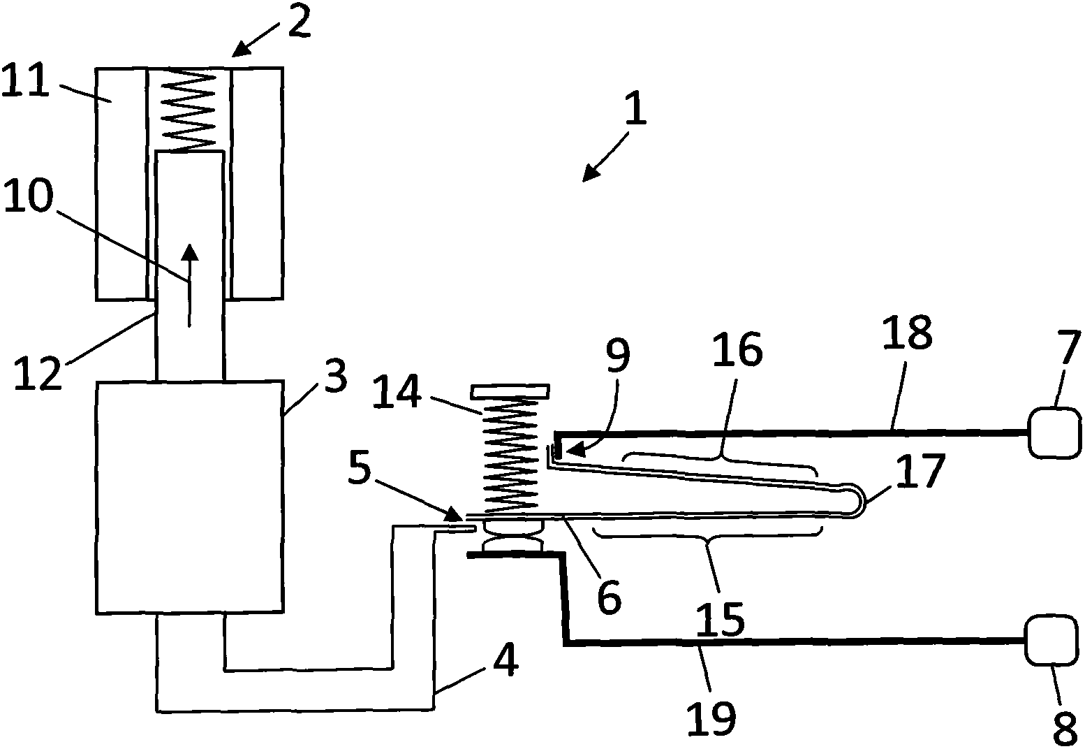
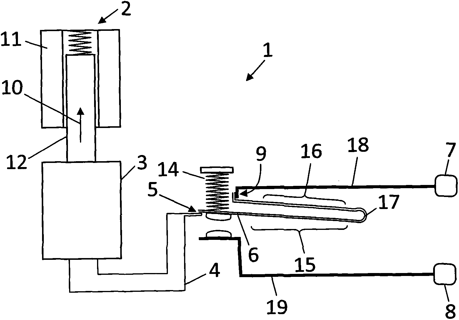
[0024] The schematic diagram of the embodiment of the relay 1 according to the invention is in Figure 1A with 1B Shown in. Relay with Figure 1A The first position (also called the closed position) in Figure 1B The second position (also called the interrupt position) in the description.

[0025] The relay includes a latch starter 2, a latch 3 and a relay starter 4 mechanically connected to the contact spring 6. The contact spring is installed between the first relay terminal 7 and the second relay terminal 8. It can be in the first position where the circuit is closed between the two relay terminals 7, 8 ( Figure 1A ) And the second position where the circuit is interrupted between the two relay terminals 7 and 8 ( Figure 1B ). In the illustrated embodiment, the first end 9 of the contact spring is connected to the conductor 18, and the conductor is interconnected with one of the contact spring and the relay terminal; the second free end 5 of the contact spring is attached Th...


PUM


Abstract

The present invention relates to a relay (1) and to an electricity meter with a relay. The relay comprises a latch actuator (2), possible a linear solenoid-based actuator, and a mechanical latch (3) operable to cyclic switch between a first latch position and a second latch position. A relay actuator (4) is coupled to the latch to follow a movement of the latch, and to a contact spring (6) which closes or interrupts an electric circuit between a first and a second relay terminal (7, 8). The contact spring is part of a conductor path (15-18), where the conductor path comprises at least one bend (17) so that the conductor path comprises a first section (15) and a second section (16) facing each other.

Description

Technical field [0001] The invention relates to relays and electric meters equipped with relays. Background technique [0002] A relay is an electrically operated switch, usually electromagnets are used to mechanically operate the switch mechanism, and a variety of different switch mechanisms are used. The so-called latching relay is one form of the relay. It has two slack states. These two states are turned on by the power supply. When the power is turned off, the latching relay retains the previous state. [0003] Known relays (such as those disclosed in GB 2 383 469 A1) include a contact reed that closes or interrupts the circuit between the first and second relay contacts. The relay contains a switch mechanism, which uses a permanent magnet in the form of an H-shaped armature. With the permanent magnet as the center, the permanent magnet is placed on the two yokes of the magnetizing coil. When the magnetic pole of the magnetizing coil is reversed, the permanent magnet is use...

Claims


Application Information

Patent Timeline
IPC IPC(8): H01H45/00H01H50/16G01R11/00
CPCH01H51/084H01H50/56H01H1/26H01H50/58
Inventor C・韦斯特J・T・汉森
Owner KAMSTRUP
Why Eureka
Try Eureka