Connector arrangements for shielded electrical cables

A technology for shielding cables and cables, which is applied to the parts, connections, and fixed connections of connecting devices, and can solve problems such as unsuitable batch termination technology.

Active Publication Date: 2013-01-09
3M INNOVATIVE PROPERTIES CO
View PDF6 Cites 18 Cited by
  • Summary
  • Abstract
  • Description
  • Claims
  • Application Information

AI Technical Summary

Problems solved by technology

Both of these general types of cables usually require the use of specially designed connectors for termination and are generally unsuitable for the use of mass termination techniques, that is

Method used


Image

  • Connector arrangements for shielded electrical cables
  • Connector arrangements for shielded electrical cables
  • Connector arrangements for shielded electrical cables

Examples


example

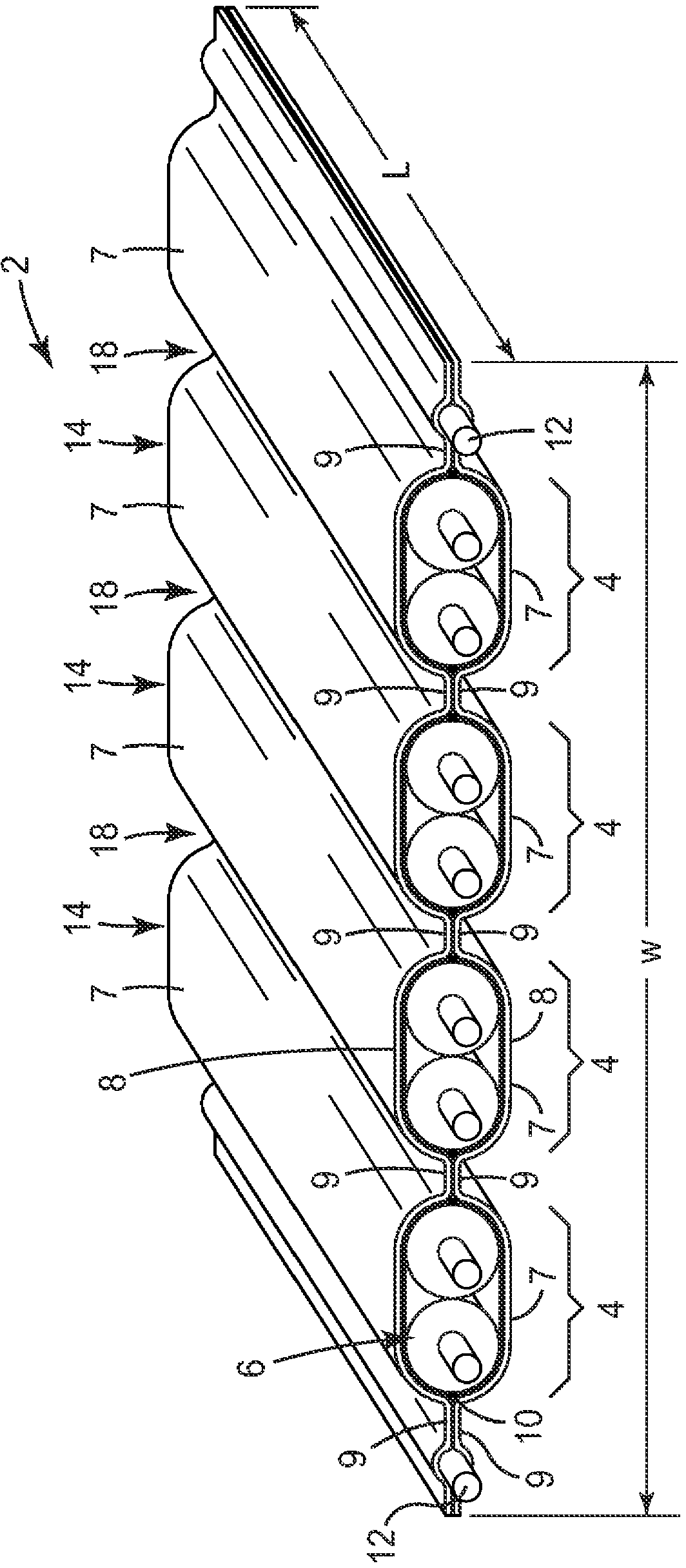
[0314] Manufactured with cable 11402 (see Figure 30a) general layout of shielded ribbon cables. The cable utilizes sixteen insulated 32 wire gauge (AWG) wires arranged in eight twinax pairs (for signal wires), and two uninsulated 32 (AWG) wires (for signal wires) along the edge of the cable (for on the drain wire). Each of the sixteen signal wires used had a silver plated solid copper core. The two drain wires each had a twisted wire construction (7 strands each) and were tinned. The insulator of the insulated wire has a nominal outside diameter of 0.025 inches. Feed sixteen insulated wires and two uninsulated wires into a Figure 5 In the device shown in c, it is placed between two shielding films. The shielding films were substantially identical and had the following construction: a polyester base layer (0.00048 inches thick) on which was placed a continuous layer of aluminum (0.00028 inches thick) on which was placed a continuous non-conductive Adhesive layer (0.001 ...


PUM

PropertyMeasurementUnit
Thicknessaaaaaaaaaa
Outer diameteraaaaaaaaaa
Conductor diameteraaaaaaaaaa

Abstract

Various high speed shielded cables (7001) are used in combination with a connector assembly (7000). The connector assembly (7000) includes a plurality of electrical terminations (7004a) in electrical contact with the conductor sets (7005) of the cable (7001)at a first end (7007) of the cable (7001), the electrical terminations (7004a) configured to make electrical contact with corresponding mating electrical terminations of a mating connector and at least one housing (7002) configured to retain the plurality of electrical terminations (7004a) in a planar, spaced apart configuration.

Description

technical field [0001] The present invention generally relates to cables and connectors. Background technique [0002] Cables for transmitting electrical signals are well known. One common type of cable is coaxial cable. Coaxial cables typically include electrical conductors surrounded by an insulator. The wire and insulator are surrounded by a shield, and the wire, insulator and shield are surrounded by a sheath. Another common type of electrical cable is a shielded electrical cable comprising one or more insulated signal conductors surrounded by a shield, eg formed of metal foil. To facilitate electrical connection of the shield, additional uninsulated conductors are sometimes provided between the shield and the insulator of one or more signal conductors. Both of these general types of cables usually require the use of specially designed connectors for termination and are generally unsuitable for the use of mass termination techniques, that is, the simultaneous connect...

Claims


Application Information

Patent Timeline
IPC IPC(8): H01B7/08H01B11/00H01R12/59
CPCH01B11/002H01B7/0838H01B11/1869H01B11/203H01B7/0861H01B7/08H01B11/00H01R12/59H01B7/02H01B7/0807H01B7/0823H01B11/005H01R13/6592
Inventor 道格拉斯·B·贡德尔威廉·V·巴拉德亚历山大·W·巴尔约瑟夫·N·卡斯蒂廖内威廉·J·李马克·M·莱坦耶西·A·门理查德·J·谢勒查尔斯·F·斯特利
Owner 3M INNOVATIVE PROPERTIES CO
Why Eureka
Try Eureka