Separation and reunion automatic control mechanism of spring machine clutch

A clutch and spring machine technology, which is applied in the field of spring machine clutch clutch automatic control mechanism, can solve problems such as narrow application range, and achieve the effects of low slip rate, high-performance clutch, and reduced wear

Inactive Publication Date: 2013-01-16
SHAOXING JIADU SPRING MACHINE
View PDF8 Cites 0 Cited by
  • Summary
  • Abstract
  • Description
  • Claims
  • Application Information

AI Technical Summary

Problems solved by technology

Although the feeding accuracy of this method is high, the scope of use is narrow. For steel wires wit

Method used


Image

  • Separation and reunion automatic control mechanism of spring machine clutch
  • Separation and reunion automatic control mechanism of spring machine clutch
  • Separation and reunion automatic control mechanism of spring machine clutch

Examples


Embodiment Construction

[0034] The present invention will be further described below in conjunction with the accompanying drawings and specific embodiments.

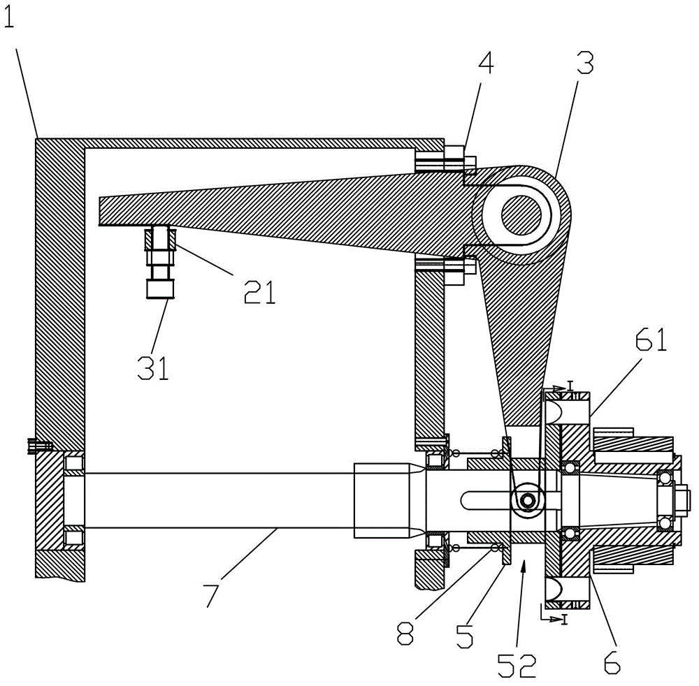
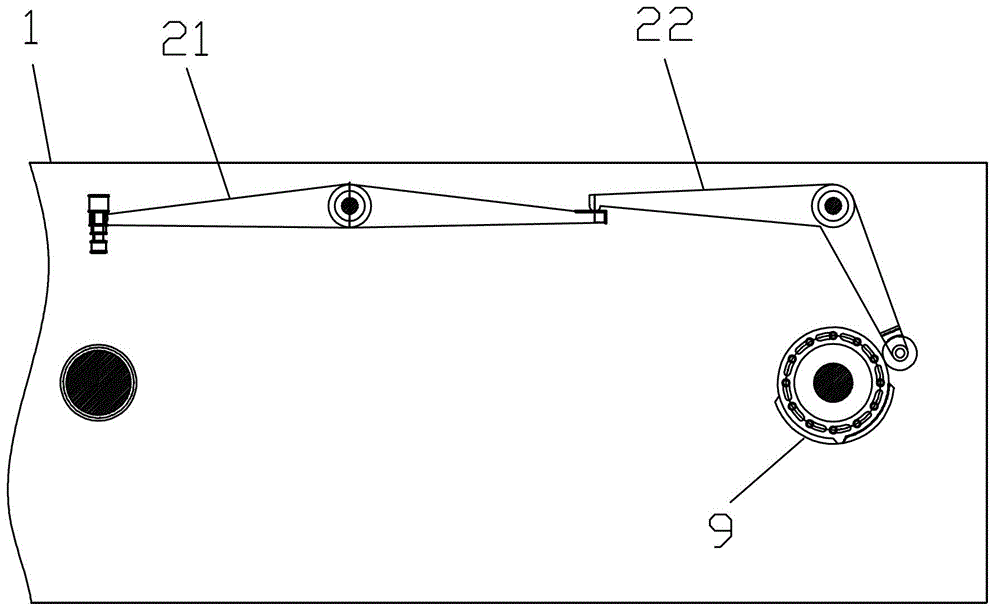
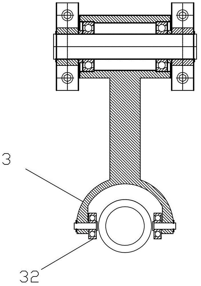
[0035] As shown in the figure, a spring machine clutch automatic control mechanism disclosed by the present invention includes a box body 1, a lever, an L-shaped shift fork 3, a support 4, a movable half clutch 5, a fixed half clutch 6, and a clutch shaft 7 , stage clip 8.

[0036] Wherein the clutch shaft 7 is arranged on the bottom of the casing 1, the movable half-clutch 5 and the fixed half-clutch 6 are all arranged on the clutch shaft 7 and are positioned outside the casing 1; some long slots 51 are provided on the movable half-clutch 5, and are arranged on the fixed half-clutch. The clutch rotating pin 61 on the clutch 6 can be inserted in the long groove 51 to realize the clutch function between the two clutches, wherein the end of the clutch rotating pin 61 in the long groove 51 has a slope structure, which is conducive to the clutch ro...


PUM


Abstract

The invention relates to the field of spring machines, in particular to a separation and reunion automatic control mechanism of a spring machine clutch. The mechanism comprises a box body, a lever, an L-shaped shifting fork, a movable semi clutch, a fixed semi clutch, a clutch shaft and a compression spring. The movable semi clutch and the fixed semi clutch are arranged on the clutch shaft, and the compression spring is further arranged between the box body and the movable semi clutch. The shifting fork is arranged on the box body, the shifting fork is arranged on the box body, the end portion of the shifting fork in the box body is connected with the lever in intersection mode and located above the lever, and the end portion of the shifting fork outside the box body is connected with the movable semi clutch in sleeve mode. Users can lift the lever to enable the shifting fork to deviate the movable semi clutch from the fixed semi clutch. By means of the scheme, the shifting fork enables the movable semi clutch to deviate from the fixed semi clutch, and the compression spring enables the movable semi clutch to be restored, and high-performance separation and reunion can be achieved.

Description

[0001] technical field [0002] [0003] The invention relates to the field of spring machines, in particular to an automatic clutch control mechanism for a spring machine. [0004] Background technique [0005] The invention belongs to the field of spring machine machinery. The traditional feeding methods of spring machines mainly consist of two types. One is to use jaw clutches, electromagnetic clutches, etc. to feed wires. The main disadvantage of this wire feeding method is the acceleration at the beginning and end of wire feeding. Both the speed and speed are infinite, and the wire feeding accuracy is not high. There is also a way that the sector gear swings back and forth and the one-way overrunning clutch cooperates to send the wire. The main advantage of this wire feeding method is that the acceleration and speed at the beginning and end of the wire feeding are all zero. Although the wire feeding precision of this method is high, the scope of application is re...

Claims


Application Information

Patent Timeline
IPC IPC(8): B21F23/00B21F35/00
Inventor 俞家林
Owner SHAOXING JIADU SPRING MACHINE
Why Eureka
Try Eureka