Positioning method for wrapped sand core and positioning structure for foundry sand core
A wrapping type and sand core technology, which is applied in the field of foundry sand cores, can solve problems such as increased production costs, reduced production efficiency, and unqualified rate of castings, and achieve the effects of reducing raw material costs, improving production efficiency, and ensuring wall thickness
- Summary
- Abstract
- Description
- Claims
- Application Information
AI Technical Summary
Problems solved by technology
Method used
Image
Examples
Embodiment 1
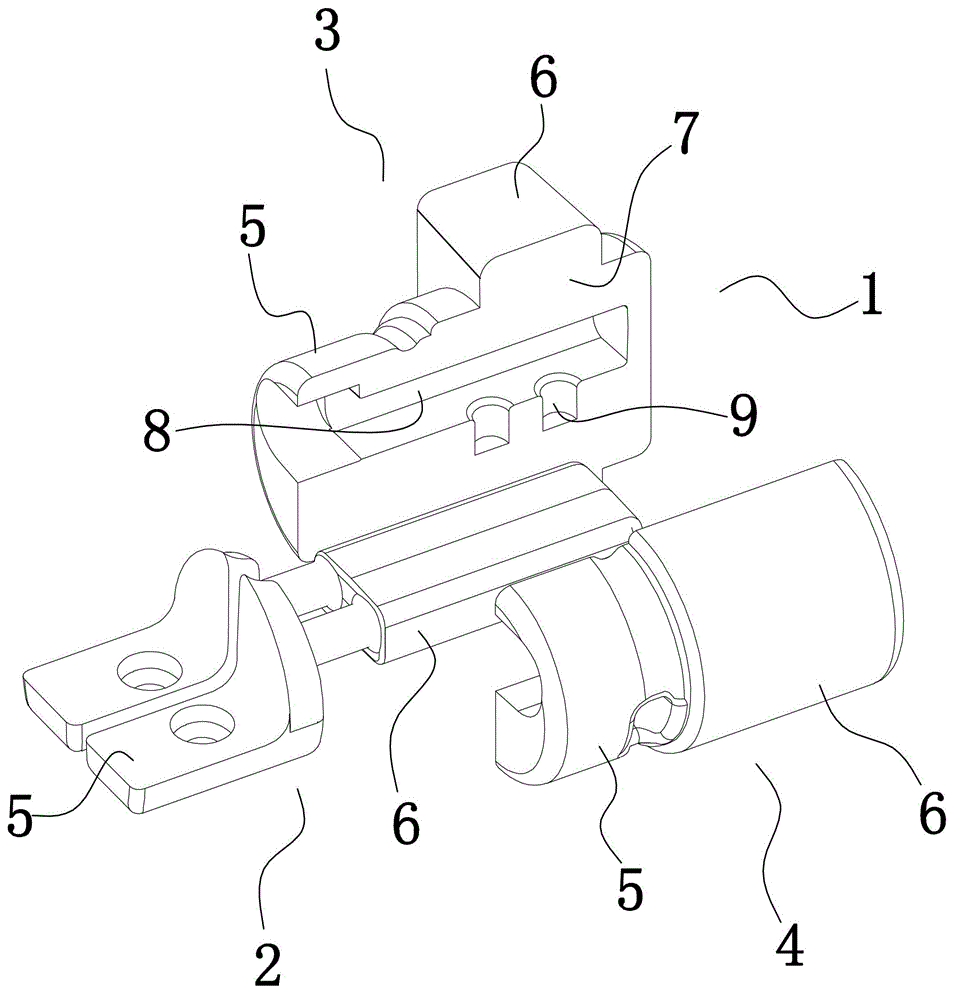
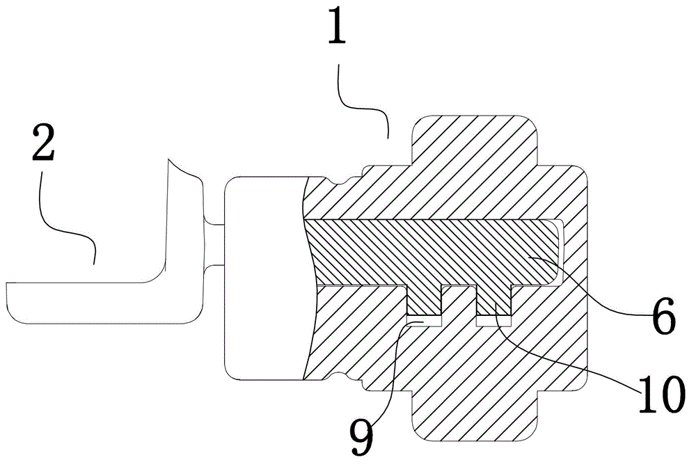
[0034] Example 1, as figure 1 , figure 2 As shown, a wrapping sand core positioning method includes a main sand core 1 and a sub-sand core 2 . Both the main sand core 1 and the sub-sand core 2 have a product forming part 5 and a fitting part 6 . The center of gravity of the sub-sand core 2 is located on the fitting portion 6 thereof.
[0035] First, the main sand core 1 is split into two parts, the first main sand core 3 and the second main sand core 4 , and a split surface 7 is formed on the first main sand core 3 and the second main sand core 4 . Both the first main sand core and the second main sand core have a product forming part 5 and a fitting part 6 .
[0036] Next, on the split surfaces 7 of the first main sand core 3 and the second main sand core 4, a limiting groove 8 for accommodating the fitting portion of the sub-sand core is provided. The limiting groove 8 extends from the fitting part 6 of the main sand core to the product forming part 5 and penetrates th...
Embodiment 2
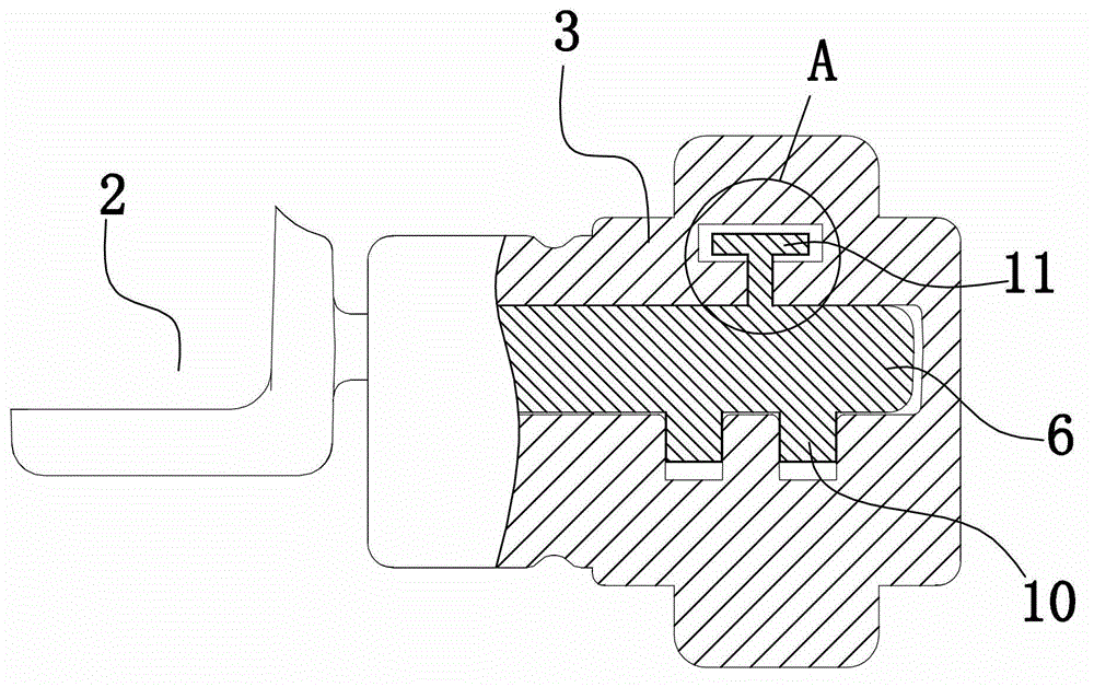
[0041] Example 2, as image 3 , Figure 4 As shown, a wrapping sand core positioning method includes a main sand core 1 and a sub-sand core 2 . Both the main sand core and the sub-sand core have a product forming part 5 and a fitting part 6 . The center of gravity of the sub-sand core 2 is located on the fitting portion 6 thereof. A raised limit block 11 is provided on one side of the sub-sand core fitting part. The limiting block is T-shaped and includes a longitudinal block 12 arranged on the sub-sand core fitting part 6 and a transverse block 13 arranged at the end of the longitudinal block.
[0042] First, the main sand core is split into two parts, the first main sand core and the second main sand core, and a split surface is formed on the first main sand core and the second main sand core. Both the first main sand core and the second main sand core have a product forming part and a fitting part.
[0043] Next, a limiting groove for accommodating the sub-sand core fi...
Embodiment 3
[0047] Example 3, as figure 1 , figure 2 As shown, a foundry sand core positioning structure includes a main sand core 1 and a sub-sand core 2, and both the main sand core and the sub-sand core are provided with a product forming part 5 and a fitting part 6. The center of gravity of the sub-sand core 2 is located on the fitting portion 6 thereof. The main sand core 1 is composed of a first main sand core 3 and a second main sand core 4, and both the first main sand core and the second main sand core have a product forming part and a fitting part; The sand core and the second main sand core are split from the main sand core, and both the split first main sand core and the second main sand core have a product forming part and a fitting part. The first main sand core 3 and the second main sand core 4 have split surfaces 7, and the first main sand core and the second main sand core have split surfaces that fit together. The split surface 7 can be parallel to or coincident wit...
PUM
 Abstract
Description
Claims
Application Information
 - R&D
- Intellectual Property
- Life Sciences
- Materials
- Tech Scout
- Unparalleled Data Quality
- Higher Quality Content
- 60% Fewer Hallucinations
Browse by: Latest US Patents, China's latest patents, Technical Efficacy Thesaurus, Application Domain, Technology Topic, Popular Technical Reports.
© 2025 PatSnap. All rights reserved.Legal|Privacy policy|Modern Slavery Act Transparency Statement|Sitemap|About US| Contact US: help@patsnap.com


