
rotary compressor

A technology of rotary compressor and compression mechanism, which is applied in the direction of rotary piston/swing piston pump components, mechanical equipment, machines/engines, etc., which can solve the problems of damaged compressors, inequalities, etc., and achieve the effect of simple processing

Active Publication Date: 2016-05-04
COPELAND CLIMATE TECN (SUZHOU) CO LTD
View PDF9 Cites 0 Cited by
  • Summary
  • Abstract
  • Description
  • Claims
  • Application Information

AI Technical Summary

Problems solved by technology

However, in the event of an insufficient supply of lubricating oil in the compressor, the amount of lubricating oil distributed to the swivel bearing and the main bearing will be significantly different, possibly resulting in an oversupply of lubricating oil for one of the main and swivel bearings and the other. Insufficient supply of lubricating oil damages the compressor

Method used


Image

  • rotary compressor
  • rotary compressor
  • rotary compressor

Examples


Embodiment Construction

[0035] The following description of preferred embodiments is exemplary only and in no way restricts the invention and its application or usage.

[0036] The inventors of the present invention found that in some vertical scroll compressors, in order to improve the lubricating oil supply to the main bearing, a transverse hole communicating with the eccentric hole is provided at a position of the rotating shaft corresponding to the main bearing. In this compressor configuration, lubricating oil can be supplied directly to the main bearing through the transverse bore and also directly to the rotary bearing through the eccentric bore extending to the top surface of the eccentric crankpin. Since the height of the transverse hole is lower than the top surface of the eccentric crank pin, lubricating oil can be more easily supplied to the main bearing. In the case of insufficient lubricant supply, the swing bearing will receive less lubricant than the main bearing, so the swing bearing...


PUM


Abstract

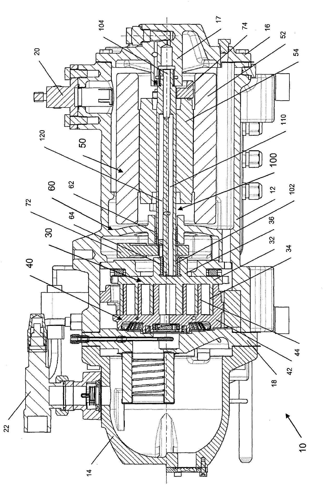
The invention relates to a rotary compressor, which comprises a shell (12), a compression mechanism, a rotating shaft (100) and a main bearing (62), wherein the compression mechanism is arranged in the shell; an eccentric crank pin (102) is arranged at the first end of the rotating shaft and drives the compression mechanism through a driving bearing (64); and the main bearing (62) is used for supporting a part of the rotating shaft. The rotary compressor is characterized in that the rotating shaft also comprises a concentric hole (104), a first eccentric hole (110), a second eccentric hole (120) and a transverse hole (130), wherein the concentric hole (104) is formed at the second end of the rotating shaft; the first eccentric hole (110) is communicated with fluid in the concentric hole and extends to the end face of the eccentric crank pin; the second eccentric hole (120) is communicated with the fluid in the concentric hole and extends to the end face of the first end of the rotating shaft; and the transverse hole (130) is communicated with the fluid in the second eccentric hole. By adopting the rotary compressor, lubricating oil flowing through the two eccentric holes can be reasonably distributed.

Description

technical field [0001] The present invention relates to a rotary compressor. Background technique [0002] A scroll compressor is one type of rotary compressor, and generally includes: a housing; a drive mechanism housed in the housing, which may include a motor and a rotary shaft; a compression mechanism driven by the rotary shaft, which may Including the movable scroll and fixed scroll that mesh with each other; the main bearing that supports the rotating shaft, etc. The rotary shaft includes a shaft body and an eccentric crank pin arranged at one end of the shaft body. An eccentric crank pin is inserted into a hub portion on the back side of the movable scroll via a rotary bearing to thereby drive the movable scroll. The rotating shaft also includes a concentric hole provided at the opposite end of the rotating shaft from the eccentric crank pin and an eccentric hole communicating with the concentric hole but eccentric with respect to the concentric hole. The eccentric...

Claims


Application Information

Patent Timeline
Patent Type & Authority Patents(China)
IPC IPC(8): F04C29/02
Inventor 苏晓耕
Owner COPELAND CLIMATE TECN (SUZHOU) CO LTD
Learn More