
Heat carrier indirect heating type carbon capture calcining furnace

A heating type, carbon capture technology, applied in the field of boilers, can solve the problems of high investment and operating costs, and achieve high-purity effects

Active Publication Date: 2022-07-15
HARBIN BOILER
View PDF5 Cites 0 Cited by
  • Summary
  • Abstract
  • Description
  • Claims
  • Application Information

AI Technical Summary

Problems solved by technology

[0003] Purpose of the present invention: In order to solve the problem that the conventional calciner adopts oxygen-enriched combustion to provide the calcining heat source, and the investment and operation costs are relatively high, the present invention proposes a heat carrier indirect heating type carbon capture calciner

Method used


Image

  • Heat carrier indirect heating type carbon capture calcining furnace
  • Heat carrier indirect heating type carbon capture calcining furnace

Examples


specific Embodiment approach 1

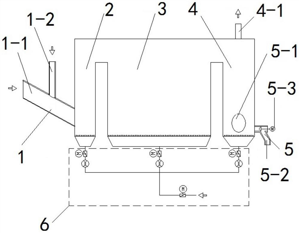
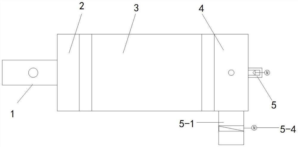
[0029] Embodiment 1: A heat carrier indirect heating carbon capture calciner, which includes an incoming material collection device 1, a premix chamber 2, a calcination reaction chamber 3, a distribution chamber 4, a discharge distribution device 5 and CO 2 Fluidized air system 6;

[0030] The incoming material collecting device 1, the premixing chamber 2, the calcining reaction chamber 3, the distribution chamber 4, and the discharging distribution device 5 are arranged in sequence from one end to the other end, and the premixing chamber 2, the calcining reaction chamber 3 and the distribution chamber 4 are all connected with the CO 2 The fluidized air system 6 is connected, and the incoming material collection device 1 is used for injecting heat carrier and carbon-carrying agent, and the heat carrier is a combustion heat source.

[0031] In this embodiment, after the carbon carrier and the heat carrier are mixed in the premixing chamber, they enter the calcination reaction ...

specific Embodiment approach 2

[0033] Specific embodiment 2: a heat carrier indirect heating type carbon capture calciner according to claim 1, one side of the upper end of the calcination reaction chamber 3 is connected to the premix chamber 2, and the other side of the upper end of the calcination reaction chamber 3 is connected The side is connected to the distribution chamber 4 .

[0034] Other embodiments are the same as the first embodiment.

specific Embodiment approach 3

[0035] Embodiment 3: A heat carrier indirect heating carbon capture calciner, the bottom of the premixing chamber 2, the bottom of the calcination reaction chamber 3 and the bottom of the distribution chamber 4 are all mixed with CO 2 The fluidized air system 6 is connected.

[0036] Other embodiments are the same as the first embodiment.


PUM


Abstract

The invention relates to the technical field of boilers, in particular to a heat carrier indirect heating type carbon capture calcining furnace, and aims at solving the problems that a conventional calcining furnace adopts oxygen-enriched combustion to provide a calcining heat source, and the investment and operation cost is high. According to the scheme, the calcining furnace comprises an incoming material collecting device, a premixing chamber, a calcining reaction chamber, a distribution chamber, a discharging distribution device and a CO2 fluidization air system; the incoming material collecting device, the premixing chamber, the calcining reaction chamber, the distribution chamber and the discharging distribution device are sequentially arranged from one end to the other end, the premixing chamber, the calcining reaction chamber and the distribution chamber are all connected with the CO2 fluidization air system, the incoming material collecting device is used for injecting a heat carrier and a carbon loading agent, the heat carrier is a combustion heat source, the heat carrier is adopted as a calcining heat source, and the discharging distribution device is used for discharging the carbon loading agent. An oxygen-enriched combustion system does not need to be arranged in the calcining furnace. And the calcining furnace adopts a fluidized bed form, and is provided with a premixing chamber, a calcining reaction chamber and a distribution chamber which are relatively independent, so that a carbon carrying agent and a heat carrier can be fully mixed, and a stable decarburization reaction is maintained.

Description

technical field [0001] The invention relates to the technical field of boilers, in particular to a heat carrier indirect heating type carbon capture calciner. Background technique [0002] Carbon capture is a technology that can directly reduce carbon dioxide emissions. Compared with the traditional EMA method, the CaO / CaCO3 carbon capture technology has the advantages of low energy consumption for regeneration, less corrosion to equipment, and low cost of raw materials. In the calcium carbon capture technology, CaCO3 needs to be heated in a calciner to release CO2 to achieve the effect of CO2 enrichment. Conventional calciners use oxygen-enriched combustion to provide calcination heat sources, so investment and operating costs are high. SUMMARY OF THE INVENTION [0003] Purpose of the present invention: In order to solve the problem that the conventional calciner adopts oxygen-enriched combustion to provide calcination heat source, and the investment and operation cost a...

Claims


Application Information

Patent Timeline
Patent Type & Authority Applications(China)
IPC IPC(8): C04B2/10C01B32/50F27B15/00F27B15/10F27B15/14
CPCC04B2/106C04B2/108C01B32/50F27B15/00F27B15/10F27B15/14
Inventor 孙向文姜孝国王德华王刚何明月朱英伟王宏志吕健
Owner HARBIN BOILER
Learn More