
Control device capable of controlling on-off of water and circuits

A control device and circuit technology, which is applied in the direction of valve operation/release device, valve device, lighting and heating equipment, etc., can solve the problems of low reliability and safety of action, high manufacturing cost, and many control parts, etc., and achieve precise action High reliability and safety, low manufacturing cost, and fewer mechanical control parts

Active Publication Date: 2013-01-16
厦门帅科卫浴电器有限公司
View PDF5 Cites 7 Cited by
  • Summary
  • Abstract
  • Description
  • Claims
  • Application Information

AI Technical Summary

Problems solved by technology

[0003] The existing control device is mainly controlled by a control circuit board, a solenoid valve, and a control switch. When the control switch sends out a signal to disconnect the water flow of the inner tank, the control circuit board first disconnects the power supply of the electric heating tube in the inner tank, and then passes the delay. The time circuit makes the solenoid valve act to cut off the water flow in the inner tank, so as to achieve the function of delaying water shutoff and taking away the waste heat of the electric heating tube, but the control circuit board of this device is more complicated, and the manufacturing cost of the solenoid valve and control switch is higher. ; On the other hand, there are many control parts, the reliability of the action and the safety of use are low

Method used


Image

  • Control device capable of controlling on-off of water and circuits
  • Control device capable of controlling on-off of water and circuits
  • Control device capable of controlling on-off of water and circuits

Examples


Embodiment Construction

[0028] The present invention will be described in further detail below in conjunction with the accompanying drawings and specific embodiments.

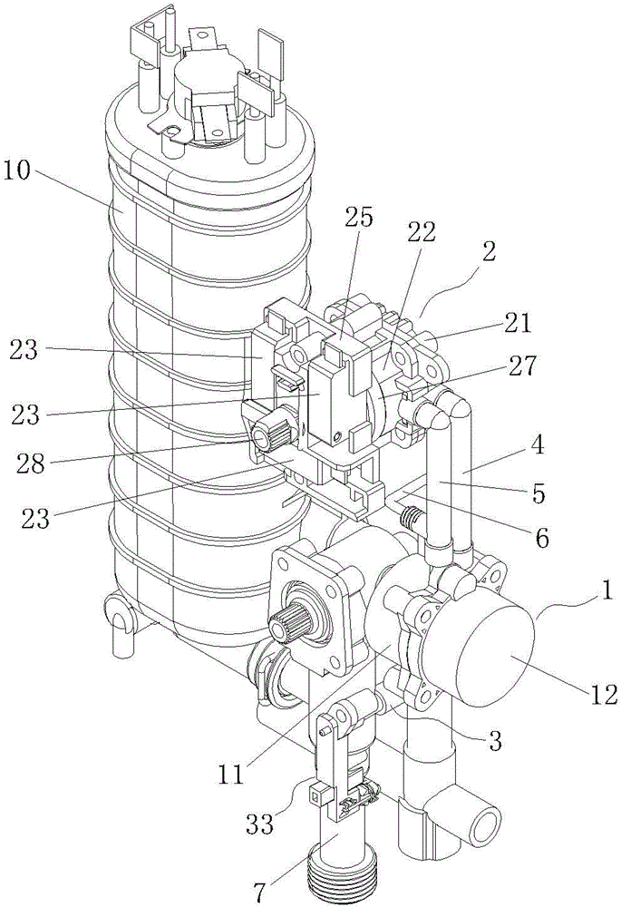
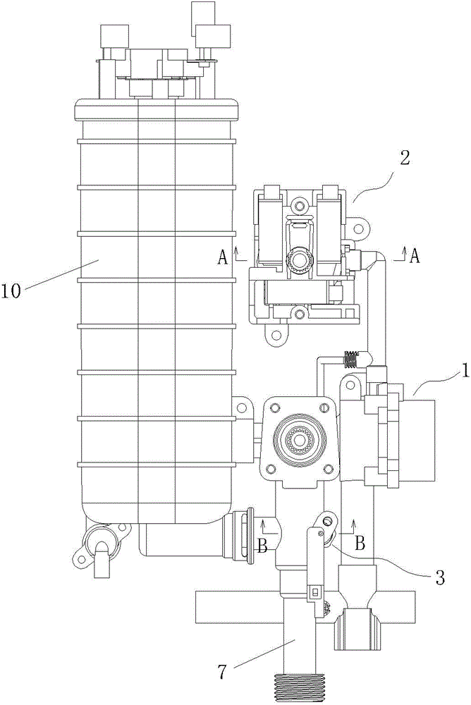
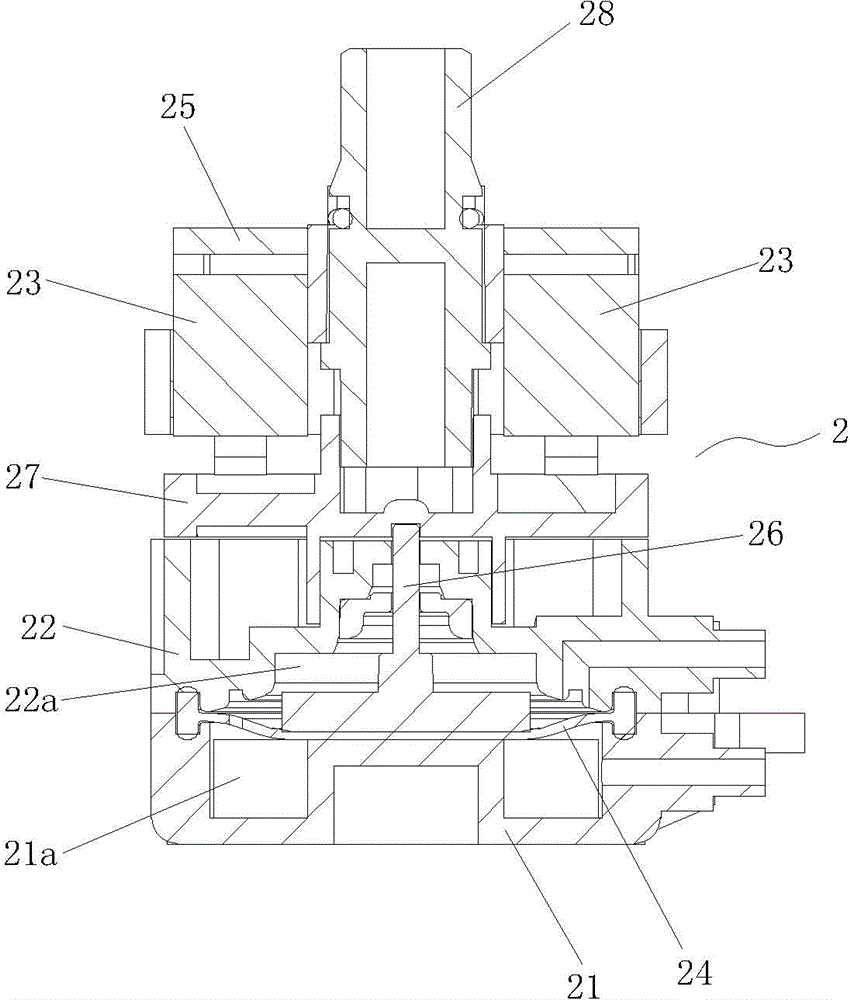
[0029] Figure 1 to Figure 8 As shown, a control device capable of controlling the on-off of the waterway and the circuit includes a waterway control mechanism 1, a circuit control mechanism 2, and a switch valve 3;

[0030] The waterway control mechanism 1 includes a valve body 11, the valve body 11 is provided with a water inlet passage 111 and a water outlet passage 112 communicating with each other, the valve body 11 is equipped with a valve cover 12, and a valve cover 12 is installed between the valve body 11 and the valve cover 12 The spool that can move relative to the bonnet 12 and the valve body water outlet channel 112, the spool isolates the inner cavity 11a of the valve body 11 from the inner cavity 12a of the bonnet 12, and the spool moves to the valve body water outlet channel 112. Seal the water outlet channel 112 of t...


PUM


Abstract

The invention discloses a control device capable of controlling on-off of water and circuits. The control device comprises a water control mechanism, a circuit control mechanism and a switch valve, the water control mechanism comprises a valve body and a valve cap, a valve core enabling an inner cavity of the valve body and an inner cavity of the valve cap to be isolated is mounted between the valve body and the valve cap, the circuit control mechanism comprises a main shell, an auxiliary shell and microswitches, an elastic diaphragm enabling an inner cavity of the main shell and an inner cavity of the auxiliary shell to be isolated is mounted between the main shell and the auxiliary shell, and a push rod is fixed on the elastic diaphragm and extends out of the auxiliary shell to correspond to the microswitches. The inner cavity of the valve body is communicated with the inner cavity of the main shell through a first water passing pipe, the inner cavity of the main shell and the inner cavity of the auxiliary shell are communicated through a second water passing pipe, the inner cavity of the auxiliary shell and the inner cavity of the valve cap are communicated through a third water passing pipe, the diameter of the second water passing pipe is larger than that of the third water passing pipe, and the switch valve is communicated with the third water passing pipe through a fourth water passing pipe. The control device has a water-off delay function, and is low in manufacturing cost and high in reliability and safety.

Description

technical field [0001] The invention relates to the technical field of manufacturing instant electric water heaters, in particular to a control device used in instant electric water heaters to control the on-off of waterways and circuits. Background technique [0002] In the field of instant electric water heater manufacturing technology, due to the high power of the electric heating tube, after opening the water flow channel of the instant electric water heater, hot water can be obtained from the water outlet of the inner tank, but in actual use, if the water outlet is closed, at the same time If the electric heating tube in the inner tank of the instant electric water heater is turned off, the residual heat of the electric heating tube will heat the temperature of the water remaining in the inner tank to a very high temperature. Therefore, it is necessary to design the function of delaying the water shut-off after the electric heating tube is powered off in the fast electr...

Claims


Application Information

Patent Timeline
IPC IPC(8): F24H9/20F16K1/00F16K31/145F16K31/44
Inventor 侯全舵曾艳王军洪壹辉陈斌王研
Owner 厦门帅科卫浴电器有限公司
Learn More