

Expansion valve components, one-way expansion valve and two-way circulation expansion valve
A technology for expansion valves and components, which is applied in the fields of expansion valve components, one-way expansion valves, two-way flow expansion valves, and mechanical automatic expansion valves. It can solve problems such as increasing energy consumption of air conditioners, increasing refrigerant resistance, and reducing service life. Effect of improving service life, reducing wear and improving life
- Summary
- Abstract
- Description
- Claims
- Application Information
AI Technical Summary
Problems solved by technology
Method used
Image

Examples
Embodiment 1
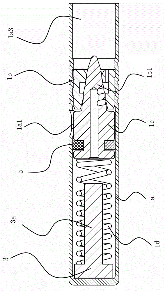
[0049] Such as figure 1 As shown, the expansion valve assembly includes a valve body 1a with an inlet 1a3 and an outlet 1a1, a valve seat 1b fixed in the valve body 1a, a valve core 1c and a spring 1d that makes the valve core 1c tend to move toward the valve seat 1b. The valve core 1c has a conical head 1c1, and the valve seat 1b is provided with a tapered hole matching the head 1c1 of the valve core 1c. Damping structure.
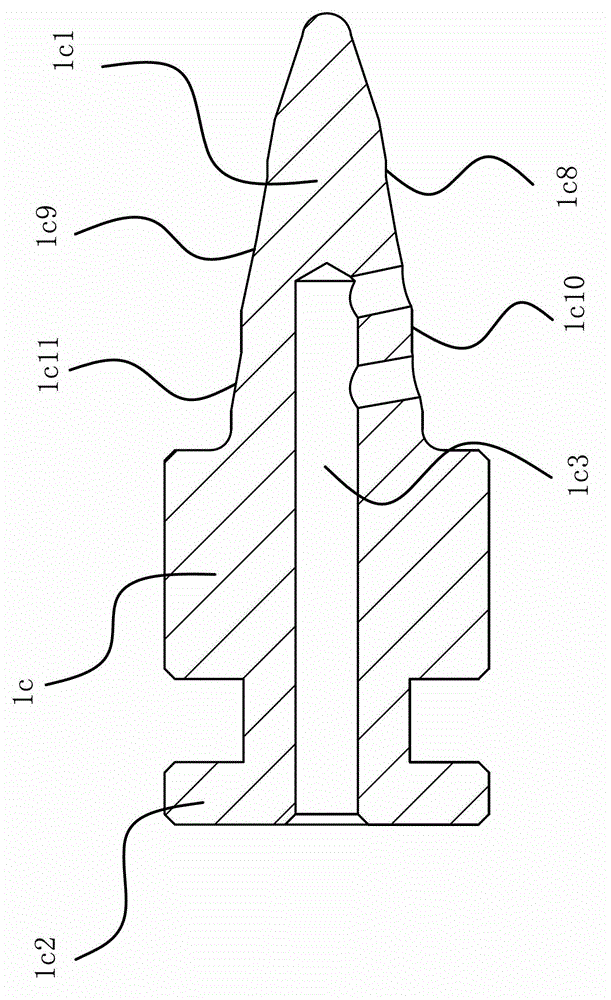
[0050] Specifically, as figure 2 , image 3 , Figure 4 As shown, the valve body 1a is straight cylindrical, the inlet 1a3 is located at the port of the straight cylindrical valve body 1a, the outlet 1a1 is opened on the side wall of the valve body 1a, and the valve core 1c also has a cylindrical shape connected with the head 1c1 of the valve core 1c. tail of 1c2. The head 1c1 of the valve core 1c has a front cylinder 1c8, a front throttling cone 1c9, a transition cone, a rear cylinder 1c10, and a rear throttling cone 1c11, and the taper hole of the...
Embodiment 2
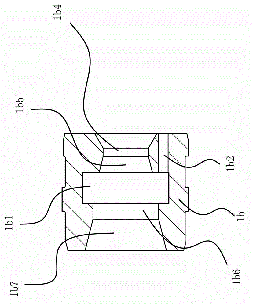
[0054] The structure and principle of embodiment two are basically similar to embodiment one, as Figure 5 As shown, the difference from Embodiment 1 lies in the damping structure. The damping structure of Embodiment 2 includes a three-way passage 1c3 opened in the valve core 1c. One end of the three-way passage 1c3 can communicate with the hollow groove 1b1, and the other end can communicate with the hollow groove 1b1. The outlet 1a1 of the expansion valve assembly 1 is in communication, and another end can communicate with the inner cavity 1a2 of the valve body 1a. Compared with the first embodiment, the setting of the throttle hole 1b2 is cancelled.
Embodiment 3
[0056] The structure and principle of embodiment three are basically similar to embodiment two, as Image 6 As shown, the difference from Embodiment 2 lies in the damping structure. The damping structure of Embodiment 3 includes a two-way channel 1c4 opened in the valve core 1c. One end of the two-way channel 1c4 can communicate with the hollow groove 1b1, and the other One end can communicate with the inner chamber 1a2 of the valve body 1a. Compared with the second embodiment, the third embodiment cancels the transmission relationship between the interior of the valve core 1c and the outlet 1a1, and directly flows through the gap between the two.
PUM
 Abstract
Description
Claims
Application Information