Refrigerator

A technology for refrigerators and storage rooms, applied in the field of refrigerators, which can solve the problems of waste and not being able to take it to the outside

Active Publication Date: 2013-01-16
MITSUBISHI ELECTRIC CORP
View PDF6 Cites 6 Cited by
  • Summary
  • Abstract
  • Description
  • Claims
  • Application Information

AI Technical Summary

Problems solved by technology

However, since the LED is accommodated in the recessed portion of the top surface, the light emitted from the LED hits the wall of the inclined surface forming the recessed portion, and this part of the light cannot be taken out, resulting in waste.

Method used


Image

  • Refrigerator
  • Refrigerator
  • Refrigerator

Examples


Embodiment approach 1

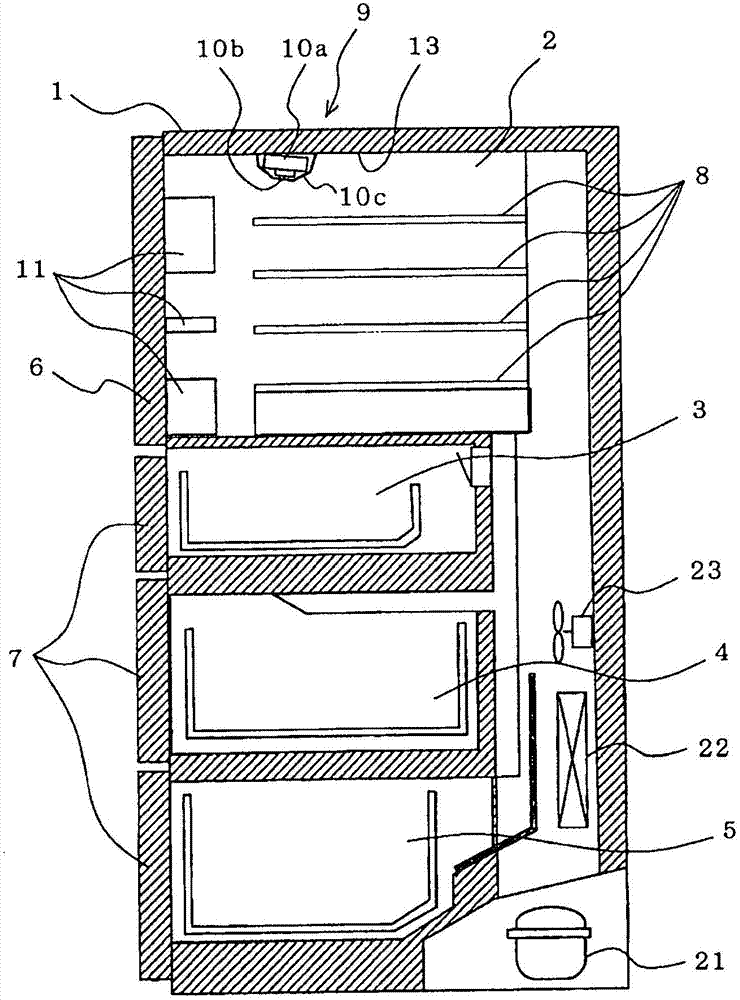
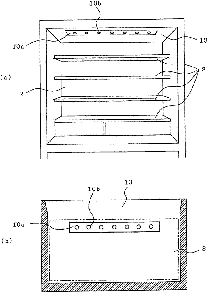
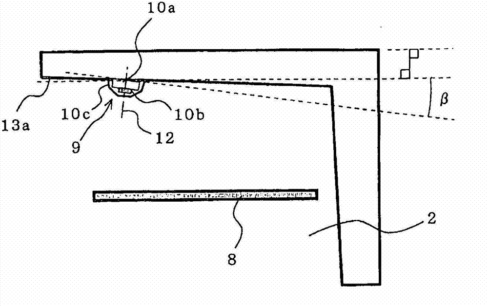
[0030] figure 1 It is a cross-sectional view showing the side of the refrigerator according to Embodiment 1 cut away. figure 2 yes figure 1 A front view of the shown refrigerator and a plan view showing the positional relationship between the lighting device and the shelf when the refrigerator is viewed from below. image 3 yes means figure 1 Side view of an example installation of the lighting device shown. Figure 4 will be image 3 An enlarged cross-sectional view of an enlarged representation of the lighting device. Figure 5 It is a directivity characteristic diagram of the light emitting diode in Embodiment 1.

[0031] The refrigerator 1 of Embodiment 1, such as figure 1 As shown, there are: a refrigerating room 2 on the uppermost floor as a storage room; a switching room 3 on the lower floor and an ice-making room (not shown) that is horizontally side by side with the switching room 3; a freezing room 5 on the lowermost floor; Vegetable room on the upper floo...

Embodiment approach 2

[0047] In Embodiment 1, the lighting device 9 is inclined toward the opening side of the refrigerator compartment 2 so that light reaches the periphery of the door pocket 11 of the refrigerator compartment 2 . On the other hand, in Embodiment 2, lighting device 9 employs a shade having a lens structure so that the light of each LED 10b is further irradiated to the back side of refrigerator compartment 2 than in Embodiment 1.

[0048] Figure 8 It is a side view showing the irradiation range of the lighting device in Embodiment 2, and a plan view showing the irradiation range of the lighting device with the upper part of the refrigerator removed. Figure 9 will be Figure 8 An enlarged cross-sectional view showing an enlarged illumination device of and an enlarged cross-sectional view showing a specific example of a lampshade having a lens structure portion. in addition, Figure 9 (a) shows the progress state of the light of each LED radiated from the globe which has a lens ...

Embodiment approach 3

[0058] In Embodiment 3, the lighting device 9 of Embodiments 1 and 2 described above is used as display means. In addition, before describing the use of the lighting device 9 as a display mechanism, refer to Figure 10 The circuit configuration of the lighting device 9 will be described.

[0059] Figure 10 It is a schematic circuit diagram showing a comparison between the lighting device in Embodiments 1 and 2 and the conventional one.

[0060] In a refrigerator using an incandescent light bulb 33 as a light source, if the door of the refrigerator compartment is opened, a door switch (not shown) provided at the opening of the refrigerator compartment is turned on, and the transistor 32 is turned on by the control device 40 . The connection action of the relay 31 is connected, and the incandescent bulb 33 is turned on. On the other hand, in Embodiments 1 and 2, if the door switch (not shown) is turned on by opening the side-by-side door 6 of the refrigerator compartment 2, ...


PUM


Abstract

The invention provides a refrigerator which can extract the light emitted out of a light-emitting diode effectively to thereby utilize the light-emitting diode furthest and then radiate light to the opening side of a refrigerating chamber. The refrigerator comprises a lighting device (9) which is configured at the downward protruded position of an inner side wall forming the top surface (13) of a storage room (2) which is equipped with an opening part at the front. The lighting device (9) comprises a substrate (10a) equipped with a plurality of light-emitting diodes (10b) along the width directions (the left and right directions) watching from the opening part side of the storage room (2), and a lampshade covering the installing sides of the light-emitting diodes (10b) of the substrate (10a). Watching from the opening part side of the refrigerating chamber, the back part of the substrate (10a) of the lighting device (9) is lower than the front part, so that the optical axes of the light-emitting diodes (10b) tilt toward the above opening part side.

Description

technical field [0001] The present invention relates to a refrigerator using light-emitting diodes as lighting in a storage room such as a refrigerator. Background technique [0002] In the past, incandescent light bulbs were mainly used as lighting devices for door pockets installed in refrigerators and refrigerator doors, but in recent years, light-emitting diodes, which are superior in terms of heat generation and power consumption, have been proposed. (hereinafter referred to as "LED") proposal. [0003] However, compared with incandescent light bulbs, LEDs have disadvantages such as small light-emitting parts, strong directivity, and narrow irradiation range. In order to fully illuminate a large refrigerator compartment with LEDs, it is necessary to use relatively bright and expensive LEDs, which tend to increase manufacturing costs while ensuring the same illuminance in the refrigerator compartment as incandescent bulbs. In addition, in order to make up for the short...

Claims


Application Information

Patent Timeline
Patent Type & Authority Applications(China)
IPC IPC(8): F25D11/00F25D27/00
Inventor 前田刚大和康成铃木和贵
Owner MITSUBISHI ELECTRIC CORP
Why Eureka
Try Eureka