Supercharge Your Innovation With Domain-Expert AI Agents!

Dual-axis drive mechanism and die bonder

一种双轴驱动、结合器的技术,应用在电固体器件、半导体器件、半导体/固态器件制造等方向,能够解决消耗电力增大、Z轴转矩减小、不能实现高速化等问题,达到实现高速化的效果

Active Publication Date: 2015-09-02
FASFORD TECH
View PDF7 Cites 0 Cited by
  • Summary
  • Abstract
  • Description
  • Claims
  • Application Information

AI Technical Summary

Problems solved by technology

If the torque of the Y drive shaft is increased, the power consumption will increase, and if the weight of the stator and rotor of the linear motor driven by the Z axis is reduced, the torque of the Z axis will be reduced, and the planned speed-up cannot be achieved.

Method used


Image

  • Dual-axis drive mechanism and die bonder
  • Dual-axis drive mechanism and die bonder
  • Dual-axis drive mechanism and die bonder

Examples


Embodiment Construction

[0029] Embodiments of the present invention will be described below with reference to the drawings.

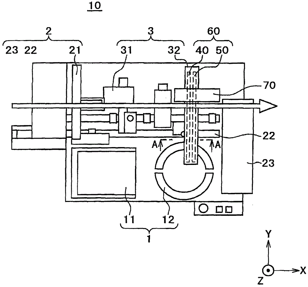
[0030] figure 1 It is a conceptual diagram of the die bonder 10 which is one embodiment of this invention seen from above. The die bonder generally has a wafer supply unit 1 , a workpiece supply and transport unit 2 , and a die bonder unit 3 .

[0031] The wafer supply unit 1 has a cassette elevator 11 and a pickup device 12 . The cassette elevator 11 has a cassette (not shown) filled with wafer rings, and sequentially supplies the wafer rings to the pickup device 12 . The picker 12 moves the wafer ring so that a desired die can be picked up from the wafer ring.

[0032] The workpiece supply and conveyance unit 2 has a stacker 21, a frame feeder 22, and an unloader 23, and conveys workpieces (substrates such as lead frames) in the direction of the arrow. The stacker 21 supplies the workpieces to which the dies are bonded to the frame feeder 22 . The frame feeder 22 conve...


PUM


Abstract

A biaxial drive mechanism including a Z axis capable of realizing a high speed elevation axis without an increment in torque on a horizontal drive axes and a die bonder using the biaxial drive mechanism is disclosed. The biaxial drive mechanism includes a handling part; a first linear motor having a first movable part that moves up / down the handling part and a first stationary part; a second linear motor having a second movable part and a second stationary part; a connecting part that directly or indirectly connects the first movable part to the second movable part via the first linear guide; a second linear guide that moves the first movable part; and a support body that fixes the first stationary part and the second stationary part with a predetermined length in parallel to each other in the horizontal direction.

Description

technical field [0001] The present invention relates to a dual-axis drive mechanism and a die bonder including an elevating shaft, in particular to a die bonder that realizes high speed and high productivity of the bonding head of the dual-axis drive mechanism including an elevating shaft. Background technique [0002] One type of semiconductor manufacturing apparatus includes a die bonder for bonding a semiconductor chip (die) to a substrate such as a lead frame. In the die bonder, the die is vacuum-adsorbed by the bonding head, raised at high speed, moved horizontally, lowered, and mounted on the substrate. In this case, it is the lift (Z) drive shaft that moves up and down. [0003] Currently, there is an increasing demand for high precision and high speed of the die bonder, and especially high speed of the bonding head which is the heart of bonding. [0004] As a technology that satisfies this requirement, there is what is described in Patent Document 1. Generally, wh...

Claims


Application Information

Patent Timeline
Patent Type & Authority Patents(China)
IPC IPC(8): H01L21/58H01L21/67
CPCH01L24/75H01L2224/83192Y10T156/1798H01L2224/7565H01L24/83Y10T156/17H01L2224/32245H01L2224/75824H01L2924/00H01L21/67132H01L21/67144H01L21/67721H01L21/6838
Inventor 保坂浩二深泽信吾
Owner FASFORD TECH
Features
  • R&D
  • Intellectual Property
  • Life Sciences
  • Materials
  • Tech Scout
  • Unparalleled Data Quality
  • Higher Quality Content
  • 60% Fewer Hallucinations
Learn More