Antenna switching method and device and wireless access point (AP)

A wireless access point and antenna switching technology, applied in the field of communication, can solve the problems of low antenna switching judgment accuracy, wrong judgment, and the antenna cannot be aligned with the STA, so as to meet the needs of a wide range, improve accuracy, and meet coverage requirements. Effect

Active Publication Date: 2013-01-16
RUIJIE NETWORKS CO LTD
View PDF3 Cites 20 Cited by
  • Summary
  • Abstract
  • Description
  • Claims
  • Application Information

AI Technical Summary

Problems solved by technology

However, using the above method, in an environment with interference, the interference will lead to judgment e

Method used


Image

  • Antenna switching method and device and wireless access point (AP)
  • Antenna switching method and device and wireless access point (AP)
  • Antenna switching method and device and wireless access point (AP)

Examples


Embodiment Construction

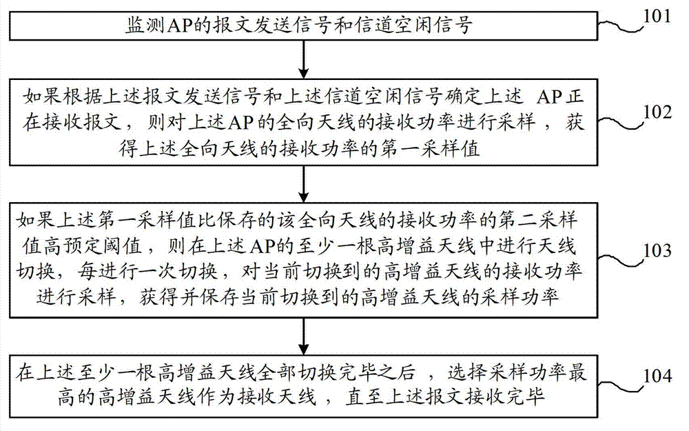
[0026] figure 1 It is a flowchart of an embodiment of the antenna switching method of the present invention, such as figure 1 As shown, the antenna switching method may include:

[0027] Step 101, monitor the message sending signal and channel idle signal of the AP.

[0028] Step 102, if it is determined that the AP is receiving the message according to the message transmission signal and the channel idle signal, then sample the received power of the omnidirectional antenna of the above AP to obtain a first sampled value of the received power of the omnidirectional antenna .

[0029] Step 103, if the above-mentioned first sampling value is higher than the predetermined threshold value of the stored second sampling value of the received power of the omnidirectional antenna, perform antenna switching among at least one high-gain antenna of the above-mentioned AP, and each time switching is performed, the The receiving power of the currently switched high-gain antenna is sampl...


PUM


Abstract

The invention provides an antenna switching method, an antenna switching device and a wireless access point (AP). The antenna switching method comprises the following steps of: monitoring a message sending signal and a channel free signal of the AP; if determining that the AP is receiving a message, acquiring a first sampled value of received power of an omnidirectional antenna; if the first sampled value is a predetermined threshold value higher than a stored second sampled value of the received power of the omnidirectional antenna, switching at least one high gain antenna of the AP, sampling the received power of the currently switched high gain antenna each time when the antennae are switched to acquire the sampled power of the currently switched high gain antenna, and storing the sampled power; and after at least one high gain antenna is completely switched, selecting the high gain antenna with the highest sampled power as a receiving antenna. By the method and the device, antenna switching judgment accuracy can be improved, uplink power from a station to the AP is increased, and the requirement on wide coverage can be met.

Description

technical field [0001] The present invention relates to communication technology, in particular to an antenna switching method, device and wireless access point. Background technique [0002] In a wireless local area network, the power of a wireless access point (Access Point; hereinafter referred to as: AP) is relatively high, while the power of a station (Station; hereinafter referred to as: STA) is relatively low. Generally, the power difference between an AP and a STA will reach more than 10dB. . Therefore, for wireless coverage, the power from STA to AP limits the range of AP wireless coverage. [0003] In the prior art, there are mainly two solutions for enhancing uplink signal power: digital signal processing (Digital Signal Processing; hereinafter referred to as: DSP) and antenna switching technology. [0004] Among them, DSP uses multiple receiving antennas to receive signals sent by STAs at the same time, and adjusts the phase and amplitude of each antenna throug...

Claims


Application Information

Patent Timeline
IPC IPC(8): H04B7/04H04B17/00H04B17/382
Inventor 陈建祥
Owner RUIJIE NETWORKS CO LTD
Why Eureka
Try Eureka