Collision-prevention device and machine tool

An anti-collision device and machine tool technology, which is applied to metal processing machinery parts, metal processing equipment, maintenance and safety accessories, etc. Long service life, working accuracy, and good impact resistance

Inactive Publication Date: 2013-01-23
SANY GRP
View PDF9 Cites 8 Cited by
  • Summary
  • Abstract
  • Description
  • Claims
  • Application Information

AI Technical Summary

Problems solved by technology

The moving parts of machine tools, such as workbenches, carriages, rams, etc., have good dynamic response and high-speed performance, but the existing

Method used


Image

  • Collision-prevention device and machine tool
  • Collision-prevention device and machine tool
  • Collision-prevention device and machine tool

Examples


Example Embodiment

[0042] It should be pointed out that the description and sequence of specific structures in this section are only descriptions of specific embodiments, and should not be considered as limiting the protection scope of the present invention. In addition, the embodiments in this section and the features in the embodiments can be combined with each other under the condition of no conflict.

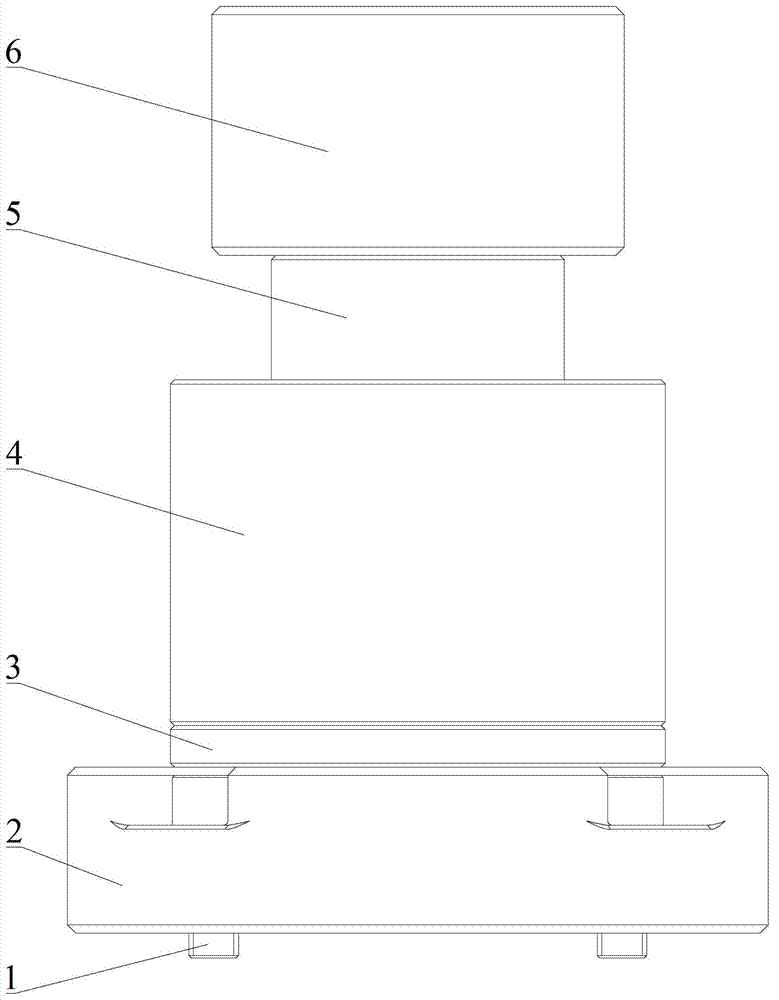
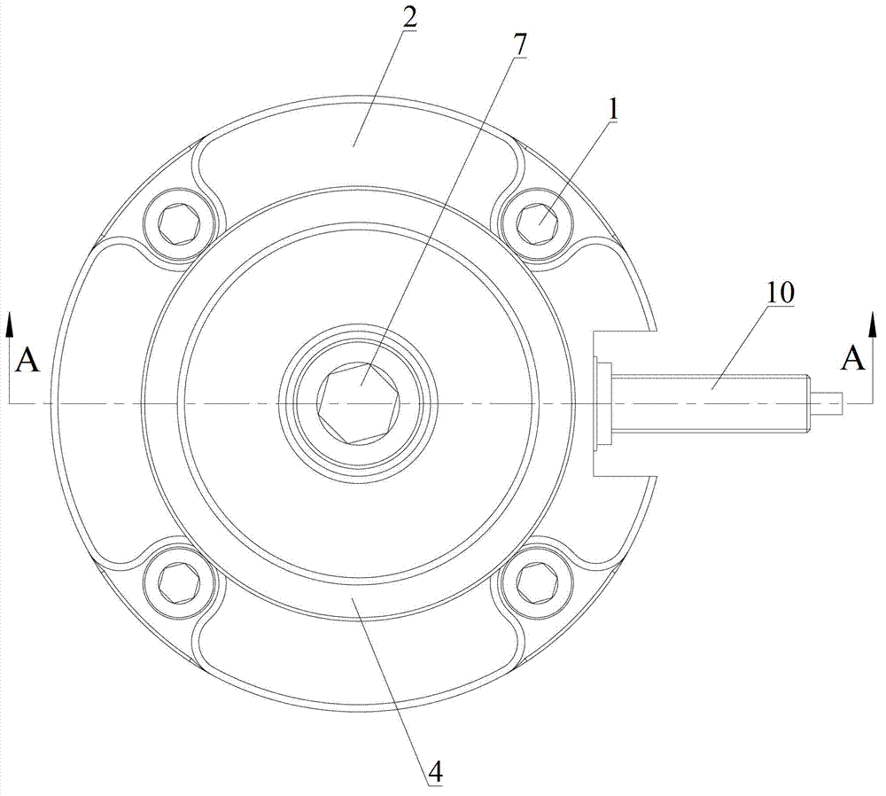
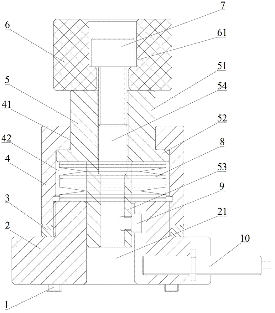
[0043] Please also refer to figure 1 , figure 2 and image 3 , Embodiment 1 of the present invention will be described in detail below in conjunction with the accompanying drawings.

[0044] As shown in the figure, the anti-collision device of this embodiment mainly includes a flange 2, an adjusting nut 3, a sleeve 4, a guide rod 5, a spring 8, and the like.

[0045] Wherein, the sleeve 4 has an inner cavity 42, the first end of the sleeve 4 is provided with a through hole 41, and the through hole 41 communicates the inner cavity 42 with the outside world; The inner wall of the second end...


PUM


Abstract

The invention relates to the technical field of machine tools, and discloses a collision-prevention device and a machine tool. The collision-prevention device comprises a socket, a guide rod and an elastic element, wherein the guide rod is telescopically arranged in the socket, and the elastic element is used for maintaining the guide rod in the extended state. With the collision-prevention device provided by the embodiment of the invention, impact energy generated by collision between a base body and a moving component during use can be effectively absorbed, the collision time is prolonged, elastic opposite force is generated, and the elastic collision between the base body and the moving component and the spacing of the moving element are realized. In addition, the entire device requires fewer components and has simple structure, easiness in assembly and good impact resistance, and the service life and the working accuracy of the moving component, the base body and relative functional components are increased.

Description

technical field [0001] The invention relates to the technical field of machine tools, in particular to an anti-collision device and a machine tool. Background technique [0002] With the continuous improvement of science and technology, machine tool products are developing in the direction of high speed, high precision and digitalization. The moving parts of machine tools, such as workbenches, carriages, rams, etc., have good dynamic response and high-speed performance, but the existing mechanical switch limit method gradually cannot meet the requirements of high-speed braking of moving parts, that is, it is easy to cause motion loss . [0003] Therefore, how to ensure that the high-speed moving parts can still be forced to stop within the controllable overtravel range when the fast accurate stop fails, so as to protect the main functional components has always been a technical problem to be solved urgently by those skilled in the art. Contents of the invention [0004] ...

Claims


Application Information

Patent Timeline
IPC IPC(8): B23Q11/00
Inventor 刘迎春刘曙光李明周振马忠良郭春亮
Owner SANY GRP
Why Eureka
Try Eureka