Micro-electrolysis reaction technique of iron carbon filler three-phase circulating fluidized bed and reactor

A technology of micro-electrolysis reactor and circulating fluidized bed, applied in chemical instruments and methods, water/sewage treatment, water/sludge/sewage treatment, etc. Carbon fillers are prone to passivation and other problems

Inactive Publication Date: 2013-01-23
东莞市珠江海咸水淡化研究所
View PDF5 Cites 11 Cited by
  • Summary
  • Abstract
  • Description
  • Claims
  • Application Information

AI Technical Summary

Problems solved by technology

[0005] However, there is a serious defect in the micro-electrolysis reaction: after a period of time when the waste water reacts with the iron-carbon filler, the iron-carbon filler is prone to passivation and hardening.
[0013] The aforementioned method of making iron-carbon filler die-casting junctions will only delay the passivation and hardening time of fillers, but cannot fundamentally solve the problems of passivation and hardening of fillers

Method used


Image

  • Micro-electrolysis reaction technique of iron carbon filler three-phase circulating fluidized bed and reactor
  • Micro-electrolysis reaction technique of iron carbon filler three-phase circulating fluidized bed and reactor
  • Micro-electrolysis reaction technique of iron carbon filler three-phase circulating fluidized bed and reactor

Examples


Embodiment 1

[0052] (a) Waste water enters below the distribution orifice of the fluidized bed, and the iron-carbon filler layer is arranged above the distribution orifice of the fluidized bed;

[0053] (b) Compressed air enters the iron-carbon filler layer at the same time;

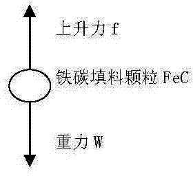
[0054] (c) Gradually increase the flow of wastewater, the iron-carbon filler layer forms a fluidized suspension layer, the iron-carbon fillers collide and rub against each other, and the pollutant components in the wastewater undergo micro-electrolysis reactions on the surface of the iron-carbon filler;

[0055] (d) The product of the micro-electrolysis reaction is taken out of the fluidized bed by the wastewater, and then enters the circulation tank for deposition;

[0056] (e) After the waste water deposits and separates the products of the micro-electrolysis reaction in the circulating tank, part of it flows out as produced water, and part of it returns to the fluidized bed as circulating waste water.

[0057] Ex...

Embodiment 2

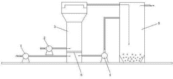
[0059] (a) The external waste water enters under the distribution orifice of the fluidized bed through the inlet pump and the circulating waste through the circulation pump, and the iron-carbon filler layer is arranged above the distribution orifice of the fluidized bed;

[0060] (b) Compressed air enters the iron-carbon packing layer through the air pump at the same time;

[0061] (c) Gradually increase the flow rate of circulating wastewater. The iron-carbon filler layer forms a fluidized suspension layer. The iron-carbon fillers collide and rub against each other in the fluidized suspension layer. The pollutant components in the wastewater of the fluidized bed are separated from the iron-carbon filler. A micro-electrolysis reaction occurs on the surface;

[0062] (d) The product of the micro-electrolysis reaction is taken out of the fluidized bed by the wastewater, and then enters the circulation tank for deposition;

[0063] (e) After the waste water deposits and separate...

Embodiment 3

[0071] The product of the micro-electrolysis reaction is deposited at the bottom of the circulation tank 5 described in this embodiment and discharged regularly, and the product water flows out from the upper part of the circulation tank 5 .

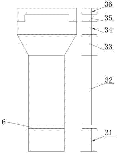
[0072] like figure 2 As shown, the fluidized bed 3 in this embodiment includes a water inlet section 31 , a distribution orifice plate 6 , a packing section 32 , an expanding section 33 , a separation section 34 , a water collection section 35 and a superelevation section 36 from bottom to top. The diameter of the water inlet section 31 and the filler section 32 is D; the height H1=0.5D of the water inlet section 31; the height H2=2D of the filler section 32; the height H3=D of the expansion section 33, The diameter is 1.5D; the height H4 of the separation section 34 = 0.5D; the height H5 of the water collection section 35 = 0.25D; the height H6 of the superelevation section 36 = 0.25D.

[0073] The water inlet section 31 plays the rol...


PUM

PropertyMeasurementUnit
porosityaaaaaaaaaa

Abstract

The invention belongs to the applied technical field of a micro-electrolysis reaction to waste water treatment, particularly relates to a micro-electrolysis reaction technique of an iron carbon filler three-phase circulating fluidized bed and a reactor. The reaction technique comprises the following steps: (a), the waste water enters the lower part of a distributing hole plate of the fluidized bed, an iron carbon filler layer is arranged at the upper part of the distributing hole plate; (b), compressed air enters the upper part of the distributing hole plate at the same time; (c), flow of the waste water is gradually increased, the iron carbon filler layer is formed to be a fluidized suspending layer, pollutant components in the waste water perform the micro-electrolysis reaction on the surface of iron carbon filler; (d), products of the micro-electrolysis reaction are taken out of the fluidized bed by the waste water and then entered a circulating tank to precipitate; (e) the waste water precipitates and separates a product carrying out the micro-electrolysis reaction in the circulating tank, part of flowed water is used as produced water, and part of the flowed water is used as circulating waste water to return to the fluidized bed. In the micro-electrolysis reaction, the invention cannot passivate, harden and block; thus the micro-electrolysis reaction technique of the iron carbon filler three-phase circulating fluidized bed can be widely industrially applied to the waste water treatment of every industry.

Description

technical field [0001] The invention belongs to the technical field of application of micro-electrolysis reaction to waste water treatment, and in particular relates to a micro-electrolysis reaction process and a reactor of an iron-carbon filler three-phase circulating fluidized bed. Background technique [0002] The micro-electrolysis reaction takes "zero-valent iron + auxiliary metal catalyst + activated carbon filler" (referred to as "iron-carbon filler") as the reaction carrier. When the wastewater passes through the iron-carbon filler under acidic conditions, the pollutant components in the wastewater are in the iron-carbon A redox reaction occurs on the surface of the filler, in which zero-valent iron acts as an anode to oxidize the pollutants and lose electrons to become Fe ++ , activated carbon acts as a cathode to undergo reduction reactions with pollutants and may produce H 2 , so the result of the overall reaction is that the wastewater pollutants are initially d...

Claims


Application Information

Patent Timeline
Patent Type & Authority Applications(China)
IPC IPC(8): C02F1/461
Inventor 袁伟光焦伟丽赵锐柏曾庆波
Owner 东莞市珠江海咸水淡化研究所
Why Eureka
Try Eureka