Combined electrical appliance panel for integrated ceiling

An integrated ceiling and combined technology, applied in covering/lining, building, building structure, etc., can solve problems such as limited scope of application, lack of uniformity, lack of structure, etc., to achieve more changes in shape and shape, installation and use The effect of convenience and simple structure

Inactive Publication Date: 2013-01-23
ZHEJIANG BAOLAN ELECTRICAL IND
View PDF6 Cites 0 Cited by
  • Summary
  • Abstract
  • Description
  • Claims
  • Application Information

AI Technical Summary

Problems solved by technology

The functional appliances of the above-mentioned integrated ceiling are generally limited to one gusset plate, such as the integrated ceiling in the bathroom, basically the heater panel, lighting panel and ventilation panel are respectively buckled on the triangular keel, but few of them have the same function. The electrical panels are combined to form a combined electrical panel, and some simply connect two lighting panels adjacent to the triangular keel, which lacks unity; and for the panel combination of ventilation and heating functions, because of Due to the limitation of the installation location of the main unit of electrical appliances, it is almost impossible to realize, especially for the indoor ceilings of some large conference rooms or offices at present, the installation of integrated ventilators, etc., can only be limited to the installation of multiple gusset panels. Assembled installation, and the gusset-shaped electrical panels are so incongruous for large-area indoor ceiling installations, the structure lacks changes in shape and shape, and the scope of application is relatively limited

Method used


Image

  • Combined electrical appliance panel for integrated ceiling
  • Combined electrical appliance panel for integrated ceiling
  • Combined electrical appliance panel for integrated ceiling

Examples


Embodiment Construction

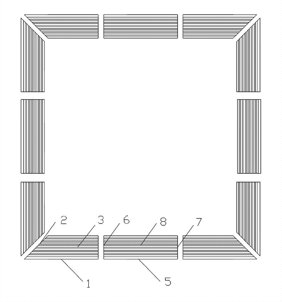
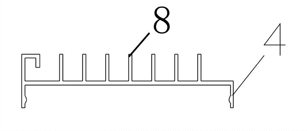
[0013] The present invention will be described in detail below in conjunction with the accompanying drawings: as shown in the figure, the present invention includes at least two square splicing panels 1 with the same structure and shape that can be buckled on the triangular keel, and one side of the square splicing panel 1 It is made into a 45-degree oblique splicing edge 2, and the other opposite side is a vertical splicing edge 3. On the surface of the square splicing panel 1, at least one group is formed on the surface of the square splicing panel 1, which is perpendicular to the vertical splicing edge 3, and is used for entering and exiting the wind. The grid hole 4 extends at least to the oblique joint side 2 or the vertical joint side 3 . The square splicing panel 1 includes square and rectangle, and the one shown in the figure is a rectangular splicing panel.

[0014] figure 1 As shown, at least one square middle panel 5 is spliced ​​between the said splicing panels 1,...


PUM


Abstract

The invention discloses a combined electrical appliance panel for an integrated ceiling. The combined electrical appliance panel comprises at least two square spliced panels which have the same structural shape and can be fastened to a triangular keel, wherein one side of the square spliced panels is manufactured into a 45-degree inclined spliced side, and the other opposite side is a vertical spliced side; at least one group of grid slots which is perpendicular to the vertical spliced side and is used for air inlet and outlet is formed on the surface of the square spliced panels; the grid slots at least extend to the inclined spliced side or the vertical spliced side; at least one square middle panel is spliced between the spliced panels; two sides of the middle panel are flat end face spliced sides; a group of middle grid slots which is perpendicular to the flat end faces on two sides and corresponds to the grid slots is formed on the surface of the middle panel; and the middle grid slots respectively extend to the spliced sides of the flat end faces on two sides. The combined electrical appliance panel is characterized by being assembled into a functional electrical appliance panel suitable for a large-area indoor ceiling and structurally realizing diversified shapes and styles, along with simple structure and convenience in use and installation.

Description

technical field [0001] The invention relates to a combined electrical panel for an integrated suspended ceiling, which belongs to the technical field of indoor suspended ceilings. Background technique [0002] Existing indoor suspended ceilings are mainly composed of triangular keels and plane gussets, and functional appliances such as lighting fixtures, ventilation fans or heaters are usually arranged on the indoor suspended ceilings. With the development of ceiling technology, the indoor ceiling seen in the market has integrated various functional electrical appliances on the ceiling surface to form an integrated ceiling. The functional electrical appliances are divided into electrical hosts and electrical panels. Installed in the indoor ceiling, the electrical panel is made into a gusset shape and is fastened to the triangular keel under the electrical main unit. The functional electrical appliances of the above-mentioned integrated ceiling are generally limited ...

Claims


Application Information

Patent Timeline
Patent Type & Authority Applications(China)
IPC IPC(8): E04F13/074
Inventor 陈建明
Owner ZHEJIANG BAOLAN ELECTRICAL IND
Why Eureka
Try Eureka