Single-column type advance support device of blasting work surface
A technology of advanced support and working face, which is applied in the direction of pillars/brackets, roof beams supporting mine roofs, mining equipment, etc., which can solve problems such as poor applicability, high cost, and complex structure, and achieve low cost, simple operation, and The effect of simple structure
- Summary
- Abstract
- Description
- Claims
- Application Information
AI Technical Summary
Problems solved by technology
Method used
Image

Examples
Embodiment 1
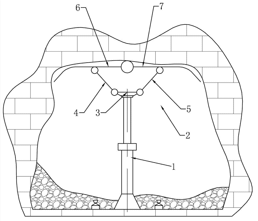
[0017] like figure 1 As shown, the single-column advanced support device for the blasting working face of the present invention includes a single hydraulic prop 1, a support top beam mechanism 2 is fixedly installed on the top of the single hydraulic prop 1, and a bottom end of the single hydraulic prop is installed with a Column shoes11. By installing the column shoe 11 at the bottom end of the single hydraulic prop 1, the pressure on the bottom plate can be reduced.
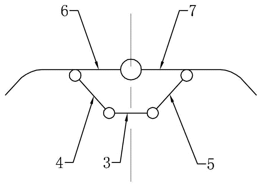
[0018] Support top beam mechanism 2 comprises the first fixed beam 3, the first left support beam 4, the first right support beam 5, the first left support beam 6 and the first right support beam 7, the middle part of the first fixed beam 3 Fixedly installed on the top of the single hydraulic prop 1, the first fixed beam 3 is perpendicular to the axis of the single hydraulic prop 1, the lower end of the first left support beam 4 is hinged with the left end of the first fixed beam 3, and the first right support...
Embodiment 2
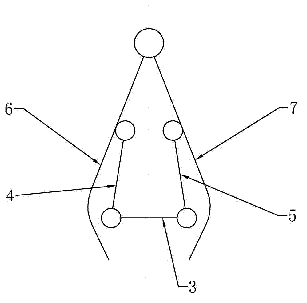
[0023] The difference between this embodiment and Embodiment 1 is that the support top beam mechanism also includes a first middle support beam, the first left support beam and the first right support beam are connected through the first middle support beam, and the first middle support beam is connected with the first middle support beam. The right end of a left support beam is hinged with the left end of the first middle support beam, and the left end of the first right support beam is hinged with the right end of the first middle support beam. By arranging the first middle support beam, the support roof beam mechanism can be adapted to a more complicated roof shape.
Embodiment 3
[0025] like Figure 4 As shown, the only difference between this embodiment and Embodiment 1 is that the support top beam mechanism 2 also includes a second left support beam 9 and a second right support beam 10, and the lower end of the second left support beam 9 is hinged on the first The middle part of the fixed beam 3, the upper end of the second left support beam 9 is hinged on the left slider, and the left slider is slidably installed on the first left support beam 6, and the left slider and the first left slider are prevented from being installed on the left slider. A locking mechanism for the relative movement of the left support beam 6, the second left support beam 9 is equal in length to the first left support beam 4, the lower end of the second right support beam 10 is hinged at the middle part of the first fixed beam 3, the second right The upper end of support beam 10 is hinged on the right slide block, and right slide block is slidably installed on the first righ...
PUM
 Abstract
Description
Claims
Application Information
 - R&D
- Intellectual Property
- Life Sciences
- Materials
- Tech Scout
- Unparalleled Data Quality
- Higher Quality Content
- 60% Fewer Hallucinations
Browse by: Latest US Patents, China's latest patents, Technical Efficacy Thesaurus, Application Domain, Technology Topic, Popular Technical Reports.
© 2025 PatSnap. All rights reserved.Legal|Privacy policy|Modern Slavery Act Transparency Statement|Sitemap|About US| Contact US: help@patsnap.com