Supercharge Your Innovation With Domain-Expert AI Agents!

Elastic pin coupler

A technology of coupling and elastic column, applied in the direction of elastic coupling, coupling, mechanical equipment, etc., can solve the problem that the wear condition of nylon pin cannot be simple, reliable, intuitive and easy to operate.

Inactive Publication Date: 2015-05-20
NANJING MEISHAN METALLURGY DEV +1
View PDF7 Cites 0 Cited by
  • Summary
  • Abstract
  • Description
  • Claims
  • Application Information

AI Technical Summary

Problems solved by technology

[0006] Aiming at the problem that the wear condition of the nylon pin in the current elastic pin coupling cannot be monitored at any time in a simple, reliable, intuitive and easy way, the present invention provides an elastic pin coupling, including an inner ring, an outer ring, and a retaining ring And the nylon pin, the outer ring is provided with a bolt hole for the nylon pin to pass through, the inner ring and the outer ring are connected through meshing teeth, the retaining ring is fixed on the outer ring by threads, and the nylon pin The pin passes through the bolt hole and is installed in the inner ring and the outer ring. An observation hole is opened on the retaining ring corresponding to the nylon pin, and the observation hole interferes with the corresponding nylon pin. Sight Covers Nylon Pin Edges

Method used


Image

  • Elastic pin coupler
  • Elastic pin coupler
  • Elastic pin coupler

Examples


Embodiment 1

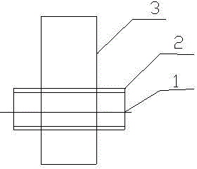
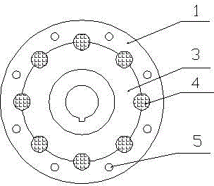
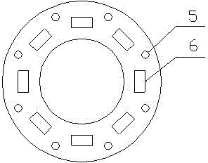
[0023] Such as Figure 1 to Figure 4 As shown, an elastic pin coupling includes an inner ring 3, an outer ring 1, a retaining ring 2 and a nylon pin 4, and the outer ring 1 is provided with a bolt hole 5 for the nylon pin 4 to pass through. The inner ring 3 is connected to the outer ring 1 through meshing teeth, the retaining ring 2 is fixed on the outer ring 1 through threads, and the nylon pin 4 is inserted into the inner ring 3 and the outer ring 1 through the bolt hole 5 , the position corresponding to the nylon pin 4 on the retaining ring 2 is provided with an observation hole 6, the observation hole 6 interferes with the corresponding nylon pin 4, and the visible range formed by the observation hole 6 covers the edge of the nylon pin 4 .

[0024] special observation Figure 4 , it can be seen that there are eight rectangular observation holes drilled along the inner circle of the retaining ring 2, and the positions of the eight rectangular observation holes 6 are exact...


PUM


Abstract

The invention relates to the field of a transmission device, in particular to a transmission device, more specifically to an elastic pin coupler. Aiming at the problem that the abrasion condition of a nylon pin in an existing elastic pin coupler cannot be simply, reliably and visually monitored at any time, the elastic pin coupler is provided. The elastic pin coupler comprises an inner ring, an outer ring, a retainer ring and a nylon pin, wherein a bolt hole for permitting the nylon pin to pass through is opened in the outer ring; the inner ring and the outer ring are connected by meshed teeth; the retainer ring is fixed on the outer ring by threads; the nylon pin passes through the bolt hole and is embedded in the inner ring and the outer ring; an observing hole corresponding to the nylon pin is arranged in the retainer ring; the observing hole is interfered by the corresponding nylon pin; and the visual range formed by the observing hole covers the edge of the nylon pin. And meanwhile, the monitoring to the easily damaged outer edges of the nylon pin and the limitation action of the retainer ring to the nylon pin are achieved.

Description

technical field [0001] The invention relates to the field of transmission equipment, in particular to a transmission device, and more specifically to an elastic pin coupling. Background technique [0002] The elastic pin coupling is a pin made of several non-metallic elastic materials, installed in the flange holes of the two halves of the coupling, and the two halves of the coupling are connected through the pins. The structure of the coupling is simple and easy It is more convenient to manufacture, assemble, disassemble and replace the elastic element, without moving the two halves of the coupling. The material of the elastic element (column pin) is generally made of nylon rod, which has the ability to compensate the offset of the two axes in a small amount. The elastic element is sheared during operation, and the work reliability is extremely poor. It is only suitable for medium-speed transmission shafting with very low requirements. It is not suitable for working condit...

Claims


Application Information

Patent Timeline
Patent Type & Authority Patents(China)
IPC IPC(8): F16D3/70
Inventor 仝浩
Owner NANJING MEISHAN METALLURGY DEV
Features
  • R&D
  • Intellectual Property
  • Life Sciences
  • Materials
  • Tech Scout
  • Unparalleled Data Quality
  • Higher Quality Content
  • 60% Fewer Hallucinations
Learn More