
Control system of electric execution mechanism

An electric actuator and control system technology, applied in engine components, mechanical equipment, valve operation/release devices, etc., can solve problems such as valve stem pull-off, reverse, valve position stroke change, etc.

Inactive Publication Date: 2013-01-23
ZHUZHOU SOUTHERN GENERAL ELECTRIC CO LTD
View PDF6 Cites 8 Cited by
  • Summary
  • Abstract
  • Description
  • Claims
  • Application Information

AI Technical Summary

Problems solved by technology

[0003] The detection of the valve position in the prior art mainly has the following disadvantages: (1) the mode of using a planetary gear plus a potentiometer is easy to cause a temperature drift, causing a change in the valve position stroke, thereby causing the valve stem to break or deform; (2) ) Hall incremental encoder, but often within a few seconds of starting, the rotation direction of the output shaft is opposite to the direction of the switch command, causing the valve stem to be bent

Method used


Image

  • Control system of electric execution mechanism
  • Control system of electric execution mechanism
  • Control system of electric execution mechanism

Examples


Embodiment Construction

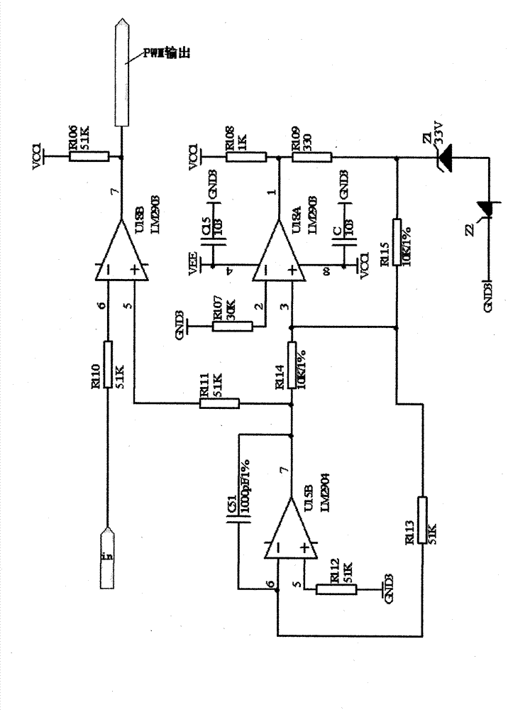
[0041] 1. Use dual-channel electronic circuit to realize torque measurement:

[0042] According to T=K*I 2 *Φ 1 *cosθ 2 For torque protection:

[0043] 1. Multiplication principle:

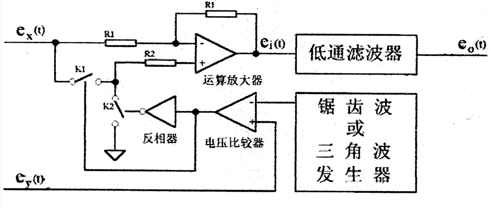
[0044] Using pulse width modulation (PWM) to realize multiplication is also called time division multiplication, which combines pulse width and amplitude modulation to realize the multiplication of two analog signals.

[0045] figure 1 It is the functional block diagram of the multiplication operation. The period T of the pulse signal output by the pulse width modulator is fixed, but the pulse width T 1 By analog signal e y modulation. by e y The modulated PWM wave controls the action of the switch K.

[0046] at T 1 During the period switch K turns on the analog signal e x , during T2=T-T1, the switch K is turned on-e x . So there are:

[0047]

[0048] According to formula (1), e can be i Think of it as a superposition of two sampling processes. Suppose two rectangular pulse ...


PUM


Abstract

The invention relates to a control system of an electric execution mechanism. The control system comprises a main control and remote control board, an analog control board, a valve position detection board, a torque detection board and a bus control board, and is characterized in that the main control and remote control board processes valve position information, torque information, a remote switching value, an analog value and a bus instruction signal inside and outside the electric execution mechanism; a circuit of the valve position detection board is a hall increment encoder or a magneto-electric absolute encoder; and the torque detection board is a double-channel electronic circuit detection board or a double-channel constant-elasticity differential stress technology detection board. A double-channel constant-elasticity differential stress technology is used for measuring torque of the electric execution mechanism without being influenced by voltage fluctuation and frequency fluctuation of a power grid; and by the technical scheme, the control system, which does not produce drift and does not damage a valve rod, of the electric execution mechanism is provided.

Description

technical field [0001] The invention relates to a motor actuator, and further relates to a control system of an intelligent motor actuator. Background technique [0002] The existing detection devices for electric actuators all have their own shortcomings when measuring torque. Although according to the motor torque formula T=K*I 2 *Φ 1 *cosθ 2 The measurement of the torque is realized by using the time division multiplier, but according to another torque formula T=9550*U*I*cosθ / n, the torque is also related to the speed n. In addition, such a processing method has disadvantages, for example, the torque measurement is also affected by grid voltage fluctuations. [0003] The detection of the valve position in the prior art mainly has the following disadvantages: (1) the mode of using a planetary gear plus a potentiometer is easy to cause a temperature drift, causing a change in the valve position stroke, thereby causing the valve stem to break or deform; (2) ) Hall incre...

Claims


Application Information

Patent Timeline
IPC IPC(8): F16K31/04F16K37/00
Inventor 肖长松
Owner ZHUZHOU SOUTHERN GENERAL ELECTRIC CO LTD
Learn More