Dynamic measurement method for radial stiffness and axial stiffness of bearing

A technology of dynamic measurement and radial stiffness, which is applied in the direction of mechanical bearing testing, etc., which can solve the problems of high equipment requirements, complex structure of the test device, and difficulty in measuring the bearing stiffness.

Inactive Publication Date: 2013-01-23
马会防
View PDF5 Cites 24 Cited by
  • Summary
  • Abstract
  • Description
  • Claims
  • Application Information

AI Technical Summary

Problems solved by technology

[0003] The test method based on Hooke's theorem belongs to the statics method. Although the principle is simple, it has high requirements on the equipment. The reason is that the bearing stiffness K is generally large, and a large force F is applied but a small displacement x is generated, which leads to the test The equipment not only needs to generate and measure a large load force, but also needs to precisely measure the extremely small displacement generated by the force, which will

Method used


Image

  • Dynamic measurement method for radial stiffness and axial stiffness of bearing
  • Dynamic measurement method for radial stiffness and axial stiffness of bearing
  • Dynamic measurement method for radial stiffness and axial stiffness of bearing

Examples


Embodiment 1

[0063] Embodiment 1: Verification of radial stiffness calculation method:

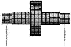
[0064] Model material density 7850 Kg / m 3 , elastic modulus 2E+11Pa, Poisson's ratio 0.3, the model structure please refer to the main parameters of the model structure in Figure 4 Example 1, the unit is mm. The finite element model of the structure was established to solve the natural frequency of the first-order lateral vibration of the test shaft under different spring stiffnesses. Some calculation results are shown in Table 1:

[0065] Table 1:

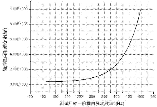
[0066] Rigidity Kr(N / m) 1E+07 2E+07 3E+07 4E+07 5E+07 6E+07 7E+07 8E+07 9E+07 1E+08 Frequency f(Hz) 98.55 137.56 166.32 189.64 209.41 226.62 241.87 255.56 267.96 279.93

[0067] Use Table 1 to fit the relationship between stiffness and frequency between 98.55 Hz and 279.93 Hz. Here, a power function is used for fitting, and the fitting function is: K r =209.06206×f 2.31959 ;

[0068] Now assume that the spring sti...

Embodiment 2

[0069] Example 2: Verification of the axial stiffness calculation method:

[0070] Model material density 7850 Kg / m 3 , elastic modulus 2E+11Pa, Poisson's ratio 0.3, the model structure please refer to Figure 8 for the main parameters of the model structure of Example 2, the unit is mm. The mass M of the structure is 16.757Kg. The finite element model of the structure is established, and the spring stiffness is set to 1E+6N / m. The natural frequency of the first-order axial vibration of the test shaft is calculated to be 38.897 Hz. Now assume that the stiffness of the spring is unknown, and use the formula to calculate the spring stiffness value, then K a =4π 2 f 2 M=4π 2 ×38.897 2 ×16.757=1000894.31N / m, compared with 1E+6N / m, the error is about 0.09%.


PUM

PropertyMeasurementUnit
Densityaaaaaaaaaa
Elastic modulusaaaaaaaaaa

Abstract

The invention belongs to the technical field of mechanical measurement and is applicable to measurement of radial stiffness and axial stiffness of bearings. The measurement principle is based on a relationship between the bearing stiffness and inherent vibration frequency of a shaft for test. The method comprises the following steps of: in the process of measuring the radial stiffness of the bearing, solving a function relationship between the radial stiffness of the bearing and the first-order transverse vibration frequency of a shaft for test, building a physical system among the shaft for test, a measured bearing and a rigid support, measuring the first-order radial vibration inherent frequency of the shaft for test, and finally, calculating the radial stiffness of the bearing according to a function relationship between the inherent vibration frequency and the radial stiffness of the bearing; and in the process of measuring the axial stiffness of the bearing, solving the mass of the shaft for test, building a physical system among the shaft for test, the measured bearing and the rigid support, measuring the first-order axial vibration inherent frequency of the shaft for test, and finally, calculating the axial stiffness of the bearing according to a relationship between the vibration inherent frequency and the axial stiffness of the bearing.

Description

technical field [0001] The invention belongs to the technical field of mechanical measurement and can be used for measuring radial stiffness and axial stiffness of rolling bearings and some sliding bearings. Background technique [0002] The measurement method of bearing stiffness is generally based on Hooke's theorem F=Kx, and the stiffness K is calculated by measuring the force F and the displacement x caused by the force. The latest patented technology on bearing stiffness testing, such as "Bearing Stiffness Testing Device" (application number: 200810137157), "air bearing stiffness testing device" (application number: 201010530570), are all testing devices based on Hooke's theorem improvements and inventions. [0003] The test method based on Hooke's theorem belongs to the statics method. Although the principle is simple, it has high requirements on the equipment. The reason is that the bearing stiffness K is generally large, and a large force F is applied but a small d...

Claims


Application Information

Patent Timeline
IPC IPC(8): G01M13/04
Inventor 马会防谌勇华宏星
Owner 马会防
Why Eureka
Try Eureka