Device, system, and method for measuring internal impedance of a test battery using frequency response

a technology of frequency response and test battery, which is applied in the field of analysis of the health of energy storage cells, can solve the problems of battery degradation over the life of the battery, battery capacity degradation, and other functional parameters, and achieve the effect of slow tuning and high resolution

Active Publication Date: 2017-09-07
BATTELLE ENERGY ALLIANCE LLC
View PDF2 Cites 30 Cited by
  • Summary
  • Abstract
  • Description
  • Claims
  • Application Information

AI Technical Summary

Problems solved by technology

Chemical changes to electrodes in a rechargeable battery may cause degradation in the battery's capacity, duration of charge retention, charging time, and other functional parameters.
Battery degradation may accumulate over the life of the battery.
Environmental factors (e.g., high temperature) and functional factors (e.g., improper charging and discharging) may accelerate battery degradation.
The resolution of existing impedance measurement systems may limit the ability to test batteries exhibiting lower internal impedance (e.g., 1 mOhm).
Other methods of impedance measurement (e.g., electrochemical impedance spectroscopy) may achieve high resolution, but may be slow to be tuned, such as requiring time on the order of about 10 minutes to obtain the measurements.

Method used


Image

  • Device, system, and method for measuring internal impedance of a test battery using frequency response
  • Device, system, and method for measuring internal impedance of a test battery using frequency response
  • Device, system, and method for measuring internal impedance of a test battery using frequency response

Examples


Embodiment Construction

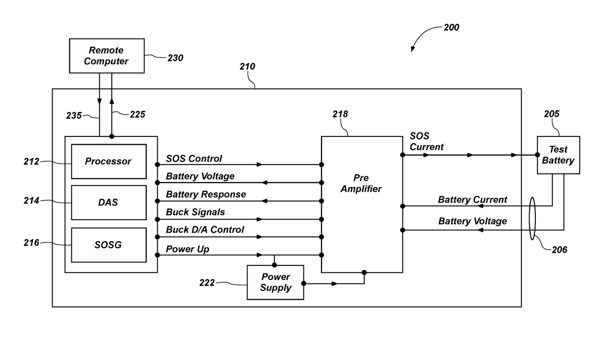
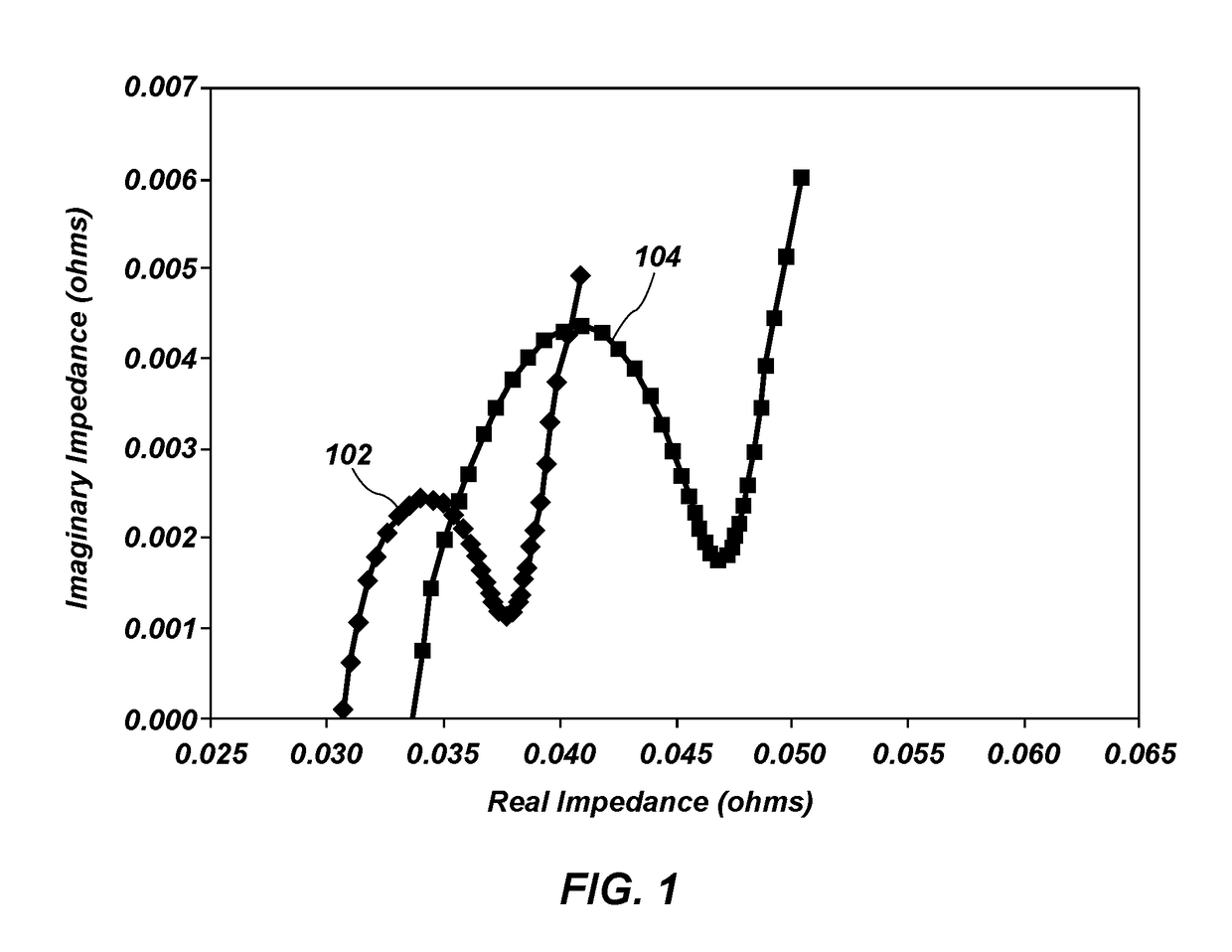
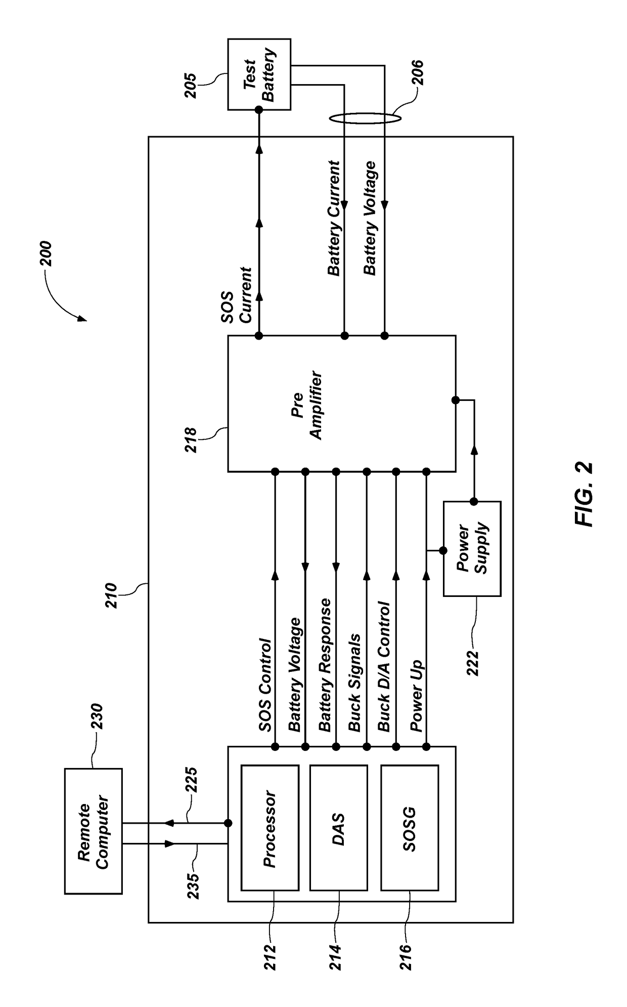
[0016]In the following detailed description, reference is made to the accompanying drawings, which form a part hereof, and in which is shown by way of illustration specific embodiments in which the present disclosure may be practiced. These embodiments are described in sufficient detail to enable those of ordinary skill in the art to practice the present disclosure. It should be understood, however, that the detailed description and the specific examples, while indicating examples of embodiments of the present disclosure, are given by way of illustration only and not by way of limitation. From this disclosure, various substitutions, modifications, additions rearrangements, or combinations thereof within the scope of the present disclosure may be made and will become apparent to those of ordinary skill in the art.

[0017]In accordance with common practice, the various features illustrated in the drawings may not be drawn to scale. The illustrations presented herein are not meant to be ...


PUM


Abstract

Battery impedance testing devices, circuits, systems, and related methods are disclosed. An impedance measurement device includes a current driver configured to generate an excitation current signal to be applied to a test battery responsive to a control signal, and a processor operably coupled with the current driver. The processor is configured to generate the control signal during an auto-ranging mode and a measuring mode. The auto-ranging mode applies the excitation current signal to the test battery over a plurality of different amplitudes to measure a response to the excitation current signal at each amplitude. The measuring mode applies the excitation current signal to the test battery for an amplitude responsive to the results of the auto-ranging mode. Improved sensitivity and resolution may be achieved for low impedance batteries with a rapid measurement time.

Description

CROSS-REFERENCE TO RELATED APPLICATIONS[0001]This application is related to U.S. patent application Ser. No. 14 / 296,321, filed Jun. 4, 2014, published as US 2014 / 0358462, pending, which claims benefit of U.S. Provisional Application 61 / 831,001, filed on Jun. 4, 2013. This application is also related to U.S. patent application Ser. No. 14 / 789,959, filed Jul. 1, 2015, pending. The disclosure of each of the foregoing applications is hereby incorporated in their entirety by this reference.STATEMENT REGARDING FEDERALLY SPONSORED RESEARCH OR DEVELOPMENT[0002]The invention was made with government support under Contract No. DE-AC07-05-ID14517, awarded by the United States Department of Energy. The government has certain rights in this invention.FIELD[0003]Embodiments of the present disclosure relate to apparatuses, systems, and methods for impedance measurement of energy storage cells, such as electrochemical cells, and more particularly, to analysis of the state of health of energy storag...

Claims


Application Information

Patent Timeline
Patent Type & Authority Applications(United States)
IPC IPC(8): G01R31/36
CPCG01R31/3679G01R31/3662G01R31/389G01R31/392Y02T10/70G01R31/382
Inventor CHRISTOPHERSEN, JON P.MORRISON, WILLIAM H.MORRISON, JOHN L.
Owner BATTELLE ENERGY ALLIANCE LLC
Why Eureka
Try Eureka