Range migration imaging method of shift invariant bi-static synthetic aperture radar

A technology of distance migration and imaging method, applied in the field of radar

Active Publication Date: 2013-01-23
UNIV OF ELECTRONICS SCI & TECH OF CHINA
View PDF0 Cites 8 Cited by
  • Summary
  • Abstract
  • Description
  • Claims
  • Application Information

AI Technical Summary

Problems solved by technology

[0005] The purpose of the present invention is to solve the above-mentioned problems existing in the existing shift-invariant

Method used


Image

  • Range migration imaging method of shift invariant bi-static synthetic aperture radar
  • Range migration imaging method of shift invariant bi-static synthetic aperture radar
  • Range migration imaging method of shift invariant bi-static synthetic aperture radar

Examples


Embodiment Construction

[0068] The present invention mainly adopts the method of simulation experiment to verify, and all steps and conclusions are verified correctly on Matlab2010. The present invention will be further described in detail with regard to specific embodiments below.

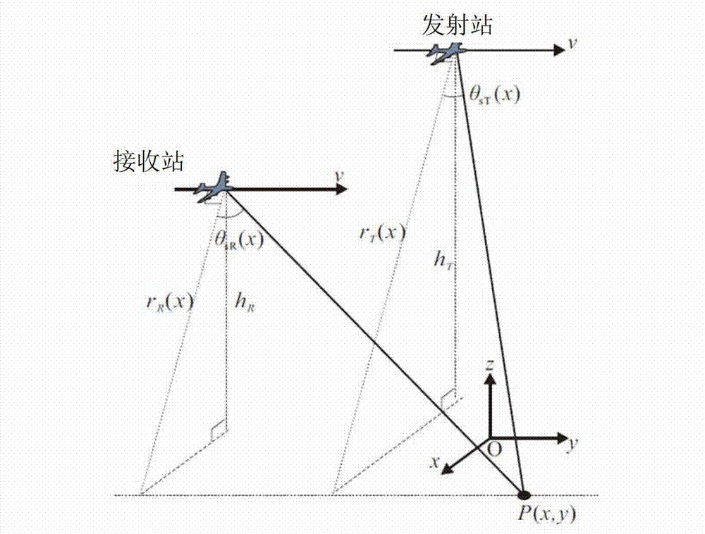
[0069] The structural diagram of the fixed station bistatic SAR system adopted in the specific embodiment of the present invention is as follows figure 1 As shown, in the Cartesian coordinate system, set the launch platform position as (x T ,y T , h T ), the zero time position of the receiving station is denoted as (x R ,y R , h R ), the speed of the receiving station is recorded as υ, the coordinates of any imaging point are marked as P(x, y), the system coordinate system is the origin of the coordinates of the imaging center point and the target O, the platform moves along the y-axis, the x-axis is the direction of the tangential track, and z The axis is vertical to the ground. Before introducing the method of ...


PUM


Abstract

The invention discloses a range migration imaging method of a shift invariant bi-static synthetic aperture radar (SAR). According to the method disclosed by the invention, the shortest slant range of the frequency spectrum phase along a receiving station is linearly expanded based on the two-dimensional frequency spectrum of the bi-static SAR of the generalized Loffeld transformation, a Stolt frequency transformation expression is derived, and the migration correction, the residual secondary range compression and the residual azimuth compression of a residual range unit are conducted through the transformation, so that the spatial linearization and the frequency linearization of the residual phase can be realized, and the shift invariant bi-static SAR can be accurately focused. Compared with the existing shift invariant bi-static SAR range migration algorithm, the method disclosed by the invention has the advantages of simple form, relatively high accuracy and relatively high operation efficiency.

Description

technical field [0001] The invention belongs to the field of radar technology, in particular to a shift-invariant bistatic synthetic aperture radar (Synthetic Aperture Radar, SAR) imaging method in synthetic aperture radar imaging technology. Background technique [0002] SAR is an all-day, all-weather modern high-resolution microwave remote sensing imaging radar. played an increasingly important role. [0003] Bistatic SAR has many outstanding advantages due to the separation of transceivers. It can obtain the non-backscatter information of the target, and has the characteristics of long range, concealment and strong anti-interference. In addition, since the bistatic SAR receiver does not contain high-power devices, it has low power consumption, small size, and light weight, and is easy to carry on various types of aircraft, and its cost is low. In a word, bistatic SAR, as a new means of space observation of the earth, has a broad space for development in many fields. ...

Claims


Application Information

Patent Timeline
IPC IPC(8): G01S13/90
Inventor 武俊杰李中余黄钰林杨海光杨建宇
Owner UNIV OF ELECTRONICS SCI & TECH OF CHINA
Why Eureka
Try Eureka