
Zooming projection lens for protection machine

A projection lens and projector technology, applied in the field of zoom projection lens, can solve the problem of insufficient light efficiency of zoom projection lens, and achieve the effect of reducing aberration and improving light efficiency

Active Publication Date: 2013-01-23
ASIA OPTICAL CO INC
View PDF6 Cites 3 Cited by
  • Summary
  • Abstract
  • Description
  • Claims
  • Application Information

AI Technical Summary

Problems solved by technology

[0006] The technical problem to be solved by the present invention is to provide a zoom projection lens that is suitable for projectors with different light sources and can avoid insufficient light efficiency in view of the defect of insufficient light efficiency of the zoom projection lens of the projector in the prior art

Method used


Image

  • Zooming projection lens for protection machine
  • Zooming projection lens for protection machine
  • Zooming projection lens for protection machine

Examples


no. 1 Embodiment

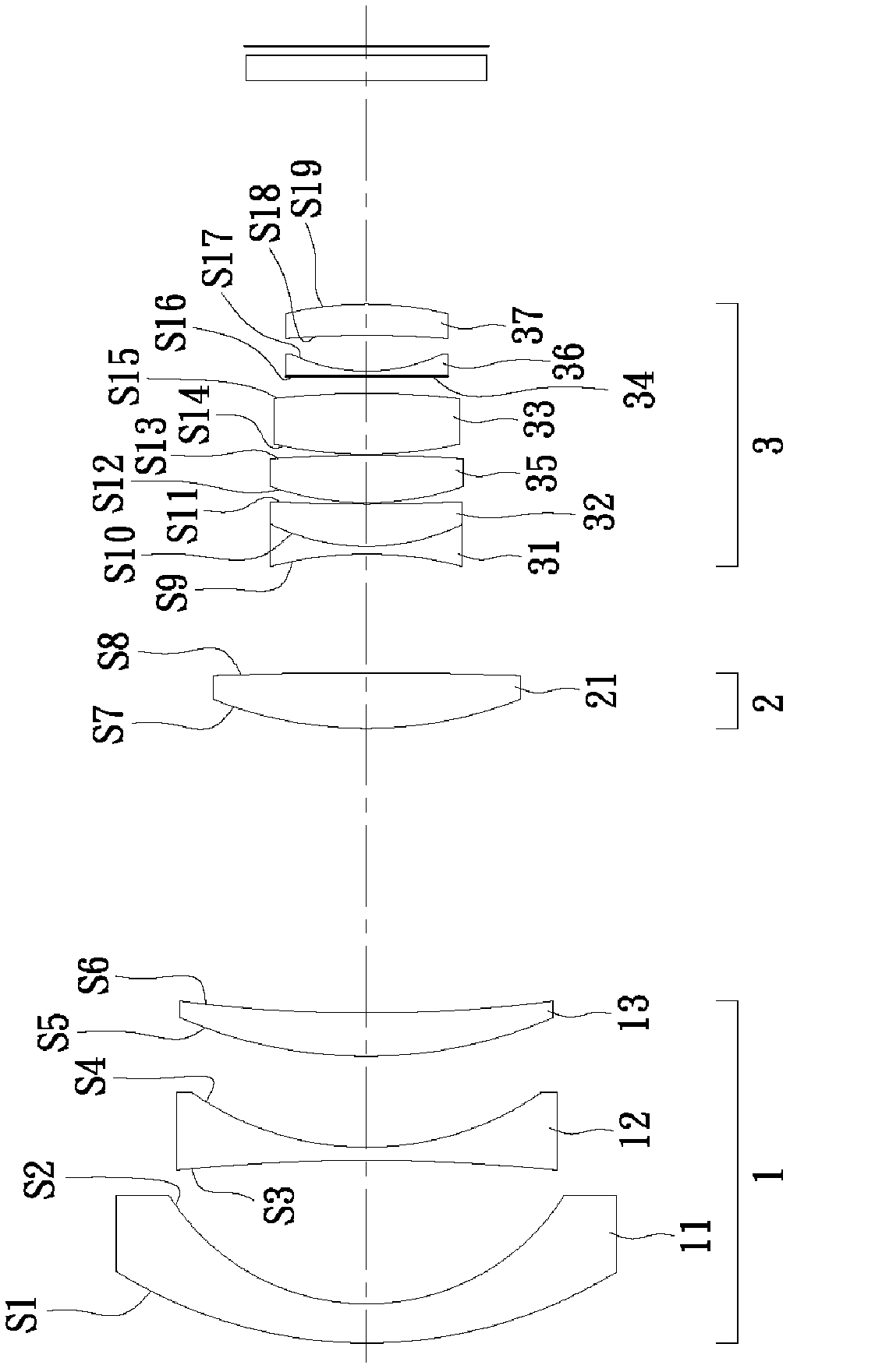
[0040] Table 1-1 shows various parameters of the first specific embodiment of the zoom projection lens. In the first specific embodiment, the convex lens 13 of the first lens group 1 is a lunar convex lens 13 (postivemeniscus) protruding toward the object end, the second lens group 2 includes a number of glass spherical biconvex lenses 21, the first The three-lens group 3 also includes a spherical biconvex lens 35 between the negative lens 31, the positive lens 32, and the aspheric lens 33, and the aperture stop 34, the spherical biconvex lens, and the aspheric lens 33 toward the image end. A concave lens 36 and a moon convex lens 37 protruding toward the image end.

[0041] The exit pupil position ex of the system is -37.6304 mm, the back focal length bf of the lens is 31.0 mm, and the focal length f of the zoom projection lens at the wide-angle end is W is 21.05041 mm, the focal length of the first lens group 1 is f 1 is -51.6057 mm, the focal length of the second lens gro...

no. 2 Embodiment

[0053] Table 2-1 shows various parameters of the second specific embodiment of the zoom projection lens. In this second specific embodiment, the convex lens 13 of the first lens group 1 is a biconvex lens 13 (biconvex), the second lens group 2 includes two glass spherical lunar convex lenses 21, and the third lens group 3 is The aperture stop 34 , spherical biconvex lens 35 ′, and spherical biconcave lens 36 ′ are further included between the mutually bonded negative lens 31 , positive lens 32 and the aspheric lens 33 .

[0054] The exit pupil position ex of the system is -42.0 mm, the back focal length bf of the lens is 31.0 mm, and the focal length f of the zoom projection lens at the wide-angle end is W is 20.6285 mm, the focal length of the first lens group 1 is f 1 is -46.3177 mm, the focal length of the second lens group is 3 f 2 is 33.9912 millimeters, the focal length f of the aspherical lens 11 in the first lens group 1 L1 Be-91.7393 millimeters, the focal length f...

no. 3 Embodiment

[0060] Table 3-1 shows various parameters of the third specific embodiment of the zoom projection lens. In this third specific embodiment, the convex lens 13 of the first lens group 1 is a plano-convex lens 13 protruding toward the object end, the second lens group 2 includes a number of glass spherical plano-convex lenses 21, and the third lens group 3 Between the mutually bonded negative lens 31, positive lens 32 and the aspheric lens 33 also includes a spherical biconvex lens 35", the aperture stop 34, a spherical lunar convex lens 36" protruding toward the object end, and a spherical biconcave lens 37 ".

[0061] The exit pupil position ex of the system is -41.737 mm, the back focal length bf of the lens is 31.0 mm, and the focal length f of the zoom projection lens at the wide-angle end is W is 23.4058 mm, the focal length of the first lens group 1 is f 1 is -48.0972 mm, the focal length of the second lens group 2 f 2 is 50.4457 millimeters, the focal length f of the a...


PUM


Abstract

The invention relates to a zooming projection lens for a projection machine. The zooming projection lens comprises a first lens set, a second lens set and a third lens set, which are sequentially arranged from an object side to an image side; the first lens set, the second lens and the third lens set are respectively of negative refractive index, positive refractive index and positive refractive index; the first lens set comprises an aspherical lens; and the third lens set comprises an aspherical lens and an aperture diaphragm. According to the zooming projection lens for the protection machine provided by the invention, the relative aperture of the zooming projection lens is reduced, and the relative aperture of the zooming projection lens at the wide angle side is less than 2.1, on the other hand, the diameter of the aperture diaphragm is increased, so that the luminous efficiency of the projection machine is improved, and moreover, the aspherical lens is utilized, so that the lens aberration due to the widening of the aperture diaphragm is reduced.

Description

technical field [0001] The invention relates to a zoom projection lens, in particular to a zoom projection lens for a projector. Background technique [0002] In recent years, cathode ray tube projection devices (Cathode Ray Tube, CRT) have been gradually replaced by thinner, lighter and smaller projection devices such as Liquid Crystal Displays (Liquid Crystal Displays) and Digital Light Processing projection devices (Digital Light Processing, DLP). [0003] Wherein, the chief ray (chiefray) of the non-telecentric system (Non-telecentric) of the digital light source processing projection device is not parallel to the optical axis, and the zoom projection lens of the non-telecentric system can be omitted compared with the zoom projection lens of the telecentric system. A total internal reflection prism to save the cost of the zoom projection lens. In addition, since the chief ray of the non-telecentric system is not parallel to the optical axis, it enters the zoom projectio...

Claims


Application Information

Patent Timeline
IPC IPC(8): G02B15/177G02B3/00G02B1/00G02B1/04
Inventor 李赞桦
Owner ASIA OPTICAL CO INC
Learn More