Magnetic rack combination

A magnetic frame and side plate technology, applied in the direction of digital processing power distribution, etc., can solve the problems of impacting the magnetic frame, inconvenient assembly, loud noise, etc., and achieve the effect of reducing noise, convenient assembly, and avoiding direct contact and collision

Inactive Publication Date: 2013-01-23
HONG FU JIN PRECISION IND (SHENZHEN) CO LTD +1
View PDF0 Cites 2 Cited by
  • Summary
  • Abstract
  • Description
  • Claims
  • Application Information

AI Technical Summary

Problems solved by technology

However, the top plate of the magnetic frame needs to be fixed on the flanges on the top of the pair of side plates by means of screw fixing or riveting, which is inconvenient to assemble; and because the hard disk is in direct contact with the inner wall of the magnetic frame, it is easy to Hit the magnetic frame, making a loud noise

Method used


Image

  • Magnetic rack combination
  • Magnetic rack combination
  • Magnetic rack combination

Examples


Embodiment Construction

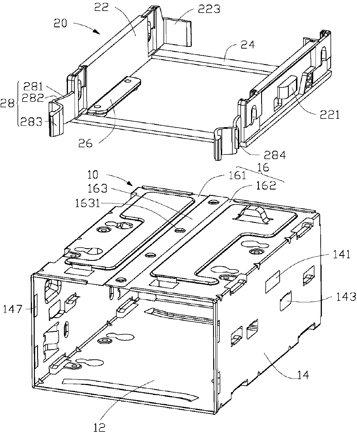
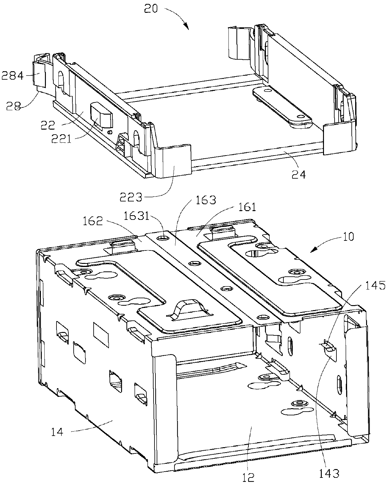
[0013] see Figure 1 to Figure 3 , The preferred embodiment of the present invention, the magnetic shelf assembly includes a magnetic shelf 10 and a tray 20 .

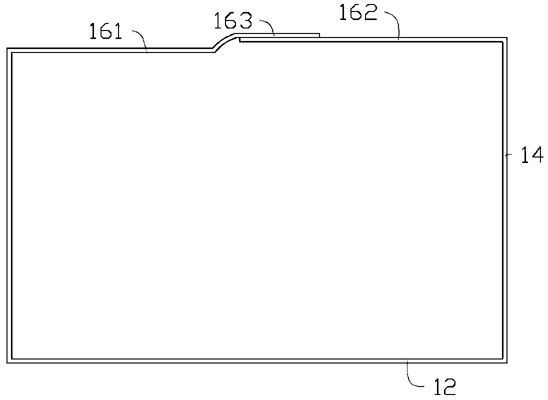
[0014] The magnetic frame 10 includes a bottom plate 12 , a pair of side plates 14 vertically extending upward from left and right side edges of the bottom plate 12 , and a top plate 16 connected between top edges of the pair of side plates 14 . The top board 16 includes a first board body 161 and a second board body 162 vertically extending from top edges of the pair of side boards 14 . The first plate 161 includes a folded edge 163 attached to the second plate 162, the folded edge 163 is provided with a number of fixing holes 1631, the second plate 162 is adjacent to the first One end of the board body 161 is also provided with a fixing hole or a fixing column corresponding to the fixing hole 1631 to facilitate fixing the folded edge 163 of the first board body 161 on the second board body 162 . In a preferred embo...


PUM


Abstract

The invention discloses a magnetic rack combination which comprises a magnetic rack, the magnetic rack comprises a baseplate, a pair of side plates and a top plate, the side plates vertically extend upwards from the opposite side edges of the baseplate, the magnetic rack combination also comprises a tray arranged in the magnetic rack and used for bearing a hard disk, the top plate of the magnetic rack comprises a first plate body and a second plate body, the first plate body vertically extends inwards from the top edge of one of the side plates, the second plate body vertically extends inwards from the top edge of the other one of the side plates, the oppositely-extended ends of the first and second plate bodies are mutually overlapped and fixed together, the tray comprises a pair of side walls respectively pressed against the side plates, each side wall is convexly provided with a bump, each side plate is provided with a fixed opening, and the bump of the tray is clamped in the fixed opening of the magnetic rack, so that the tray is fixed in the magnetic rack. The magnetic rack combination disclosed by the invention is convenient to assemble, and can reduce vibrations and noises caused by the vibrations.

Description

technical field [0001] The invention relates to a magnetic frame assembly with shock-absorbing effect. Background technique [0002] One or more hard disks are usually installed in computer equipment, and these hard disks are fixed in the computer case by shared or individual magnetic racks, and the magnetic racks include a bottom plate, a pair of side plates extending vertically upward from opposite side edges of the bottom plate and a top plate fixed on the top edge of the pair of side plates, the hard disk can be installed in the receiving space surrounded by the bottom plate, the side plates and the top plate. However, the top plate of the magnetic frame needs to be fixed on the flanges on the top of the pair of side plates by means of screw fixing or riveting, which is inconvenient to assemble; and because the hard disk is in direct contact with the inner wall of the magnetic frame, it is easy to Hitting the magnetic frame produces a loud noise. Contents of the inven...

Claims


Application Information

Patent Timeline
Patent Type & Authority Applications(China)
IPC IPC(8): G06F1/18
Inventor 丁羽辰
Owner HONG FU JIN PRECISION IND (SHENZHEN) CO LTD
Why Eureka
Try Eureka