
An adjustable mounting bracket for solar battery modules

A technology for solar cell components and fixed brackets, which is applied to electrical components, supporting structures of photovoltaic modules, photovoltaic power generation, etc., can solve the problems of wasting materials, difficult to adapt to complex terrain, labor-consuming and time-consuming, etc., to ensure reasonable layout and shortening. The effect of construction period and reduction of project investment

Active Publication Date: 2015-08-19
ENERGY CHINA YNPD
View PDF5 Cites 0 Cited by
  • Summary
  • Abstract
  • Description
  • Claims
  • Application Information

AI Technical Summary

Problems solved by technology

The fixed brackets currently used are suitable for installation on flat or relatively flat terrain conditions. They have no adjustable performance or poor adjustable performance, and it is difficult to adapt to complex terrain changes. Installation and adjustment are difficult. The main reason is that the main connecting components of the bracket The structural form does not have adjustable performance, resulting in many key nodes of the bracket not being able to adjust with terrain changes
In order to adapt to terrain changes as much as possible, the connecting components of the key nodes of the existing support will be made into multiple groups of components of different sizes, but they cannot be used in common with each other, nor can they continuously adapt to terrain changes. High precision, for the installation of thousands of brackets in a large area, it is a very labor-intensive and time-consuming thing, and it will waste a lot of materials

Method used


Image

  • An adjustable mounting bracket for solar battery modules
  • An adjustable mounting bracket for solar battery modules
  • An adjustable mounting bracket for solar battery modules

Examples


Embodiment Construction

[0027] The present invention will be further described below in conjunction with the accompanying drawings and specific embodiments.

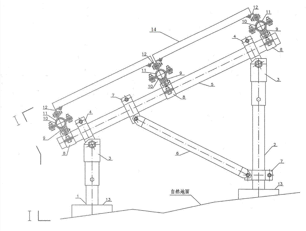
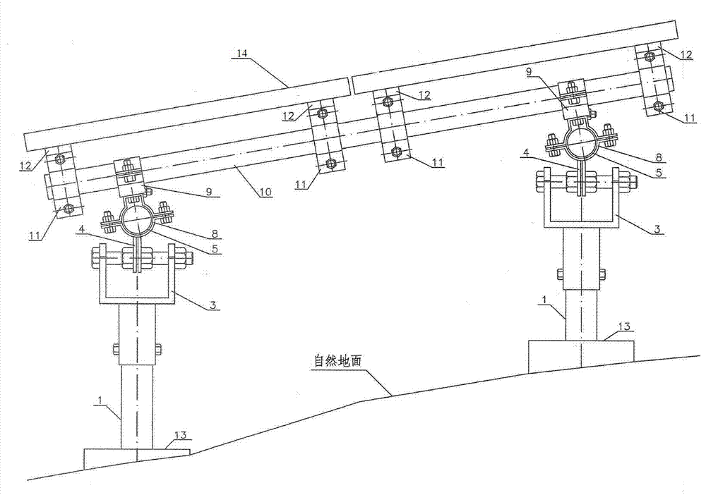
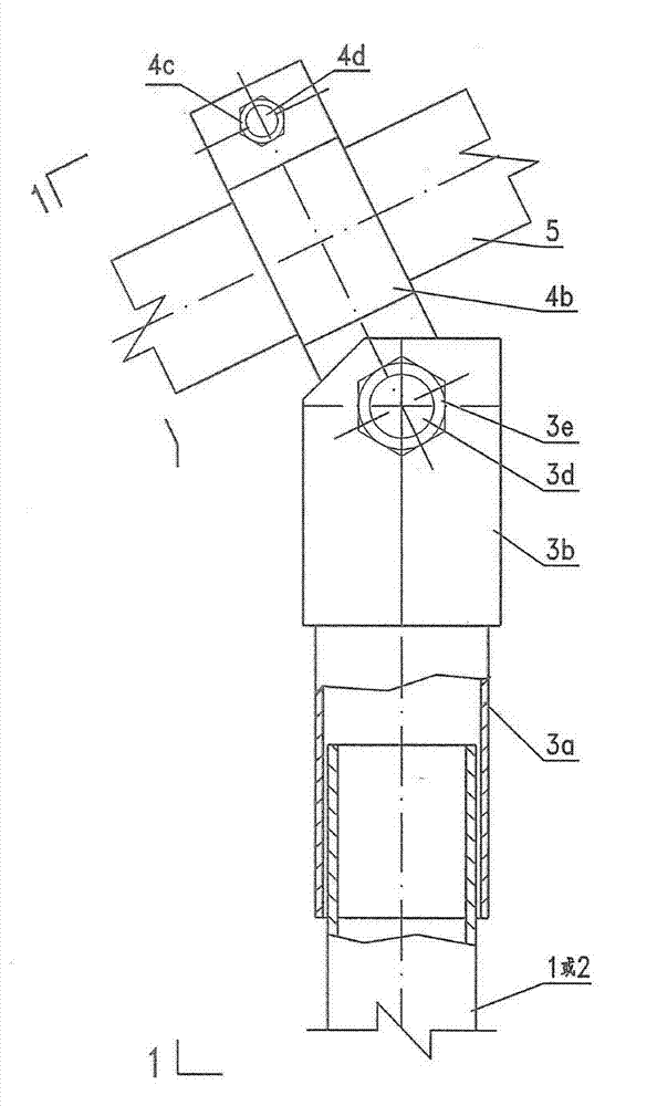
[0028] Such as figure 1 and figure 2 As shown, the lower parts of the front and rear columns 1 and 2 of the bracket are vertically connected to the foundation 13, and the upper part is set with an adjustable support 3; on the upper part of the adjustable support 3, the longitudinal beam 5 is connected to the adjustable support 3 through an arc-shaped adjustable hoop 4. Connection; on the upper part of the longitudinal beam 5, the transverse beam 10 is connected to the longitudinal beam 5 through special-shaped adjustable hoops 8 and 9; 10 connection; between the longitudinal beam 5 and the rear column 2, the diagonal brace 6 is respectively connected with the longitudinal beam 5 and the rear column 2 through the arc-shaped adjustable hoop 7.

[0029] Such as Figure 3a , Figure 3b As shown, the lower part of the adjustable support 3 is a ...


PUM


Abstract

The invention discloses an adjustably mounted solar battery component fixing bracket, which comprises a front vertical column and a rear vertical column which have circular tube structures, adjustable supports arranged on the upper parts of the front vertical column and the rear vertical column, a longitudinal beam which is arranged on the upper parts of the adjustable supports and has a circular tube structure, arc adjustable hoops, which are connected with the adjustable supports, of the longitudinal beam, transverse beams which are arranged on the upper part of the longitudinal beam and have circular tube structures, specially-shaped adjustable hoops, which are connected with the longitudinal beam, of the transverse beams, L-shaped solar battery component connection pieces arranged on the upper parts of the transverse beams, arc adjustable hoops, which are connected with the transverse beams, of the solar battery component connection pieces, an inclined strut arranged between the longitudinal beam and the rear vertical column, and arc adjustable hoops, which are connected with the longitudinal beam and the rear vertical column, of the inclined strut. Compared with the prior art, the adjustably mounted solar battery component fixing bracket has the advantages that mounting positions of the components of the bracket are easy to adjust, so that the mounting of the bracket can easily adapt to the change of a complicated stratum; and therefore, the construction working period can be shortened, materials are saved, engineering investment can be reduced, and a solar battery matrix is rationally arranged.

Description

technical field [0001] The invention relates to an adjustable fixed bracket for solar battery components. technical background [0002] The solar cell array is an important part of the photovoltaic power station, mainly composed of the bracket and the battery components installed on the bracket. The support is mainly divided into two types: fixed type and tracking type. The fixed type is currently the most widely used type of support in engineering. Under the condition of complex terrain (such as mountainous and hilly terrain), the installation and adjustability of the fixed support has a very important impact on shortening the construction period of the project, saving the project land, and reducing the project investment. The fixed brackets currently used are suitable for installation on flat or relatively flat terrain conditions. They have no adjustable performance or poor adjustable performance, and it is difficult to adapt to complex terrain changes. Installation and a...

Claims


Application Information

Patent Timeline
Patent Type & Authority Patents(China)
IPC IPC(8): H02S20/30
CPCY02E10/50
Inventor 刘新春罗彦李根森
Owner ENERGY CHINA YNPD
Learn More