
Control device of ring main unit

A control device and a technology for a ring network cabinet, applied in the power field, can solve the problems of low standardization of the ring network cabinet and complicated wiring, and achieve the effects of reducing the time for manual wiring and assembly, solving the complicated wiring and reducing errors.

Active Publication Date: 2015-10-28
BEIJING JOYO ELECTRIC CO LTD
View PDF2 Cites 0 Cited by
  • Summary
  • Abstract
  • Description
  • Claims
  • Application Information

AI Technical Summary

Problems solved by technology

[0005] The invention provides a control device of a ring network cabinet to solve the cumbersome wiring caused by the low degree of standardization of the structure of the ring network cabinet in the related art

Method used


Image

  • Control device of ring main unit
  • Control device of ring main unit
  • Control device of ring main unit

Examples


Embodiment 1

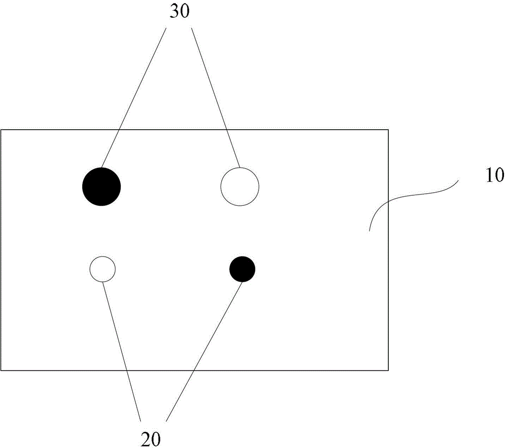
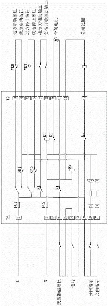
[0023] This preferred embodiment provides a control device for a ring network cabinet, figure 1 It is a schematic structural diagram of the device, which includes: a housing 10; a PCB circuit board, which is arranged in the housing 10, and the PCB circuit board is integrated with the control circuit of the ring network cabinet. Preferably, the PCB board is sealed by a sealant In the casing; the switch 20 is arranged on the casing 10, and is used to generate a trigger signal to control the opening and / or closing state of the circuit. Preferably, the above-mentioned switch includes: a closing button, which is arranged on the casing for use It is used to generate the first trigger signal to control the circuit to be in the closing state; the opening button is arranged on the housing and is used to generate the second trigger signal to control the circuit in the opening state; and the connector, the lead wire of the control device passes through the The plug-in is led out, wherein...


PUM


Abstract

The invention provides a control device of a ring main unit. The control device comprises a shell, a PCB (Printed Circuit Board), a switch and a connector assembly, wherein the PCB is arranged in the shell, and a control circuit of the ring main unit is integrated on the PCB; the switch is arranged on the shell and is used for generating a trigger signal so as to control a switching-off and / or switching-on state of the control circuit; and an outgoing wire of the control device is educed by means of the connector assembly. According to the control device disclosed by the invention, the problem of fussy wiring caused by low standardization degree of a structure mode of the ring main unit in the correlation technology is solved, the manual wiring and assembling time is prolonged, and furthermore, errors possibly existing in the manual wiring process are reduced.

Description

technical field [0001] The invention relates to the field of electric power, in particular to a control device for a ring network cabinet. Background technique [0002] As a common device in the power field, the ring main unit has a wide range of applications. The electric operation control of the existing ring network cabinet generally adopts the traditional control method, and the electrical components such as indicator lights and buttons are installed on the instrument door, and the secondary terminal block is installed in the secondary terminal room, and the traditional BVR is used for the contact wiring. BV-type wire connection, the wire harness is wound with a snakeskin tube. [0003] The existing structural mode leads to cumbersome wiring, prone to errors, and low degree of standardization, which makes it difficult to organize mass production of the product and prolongs the processing cycle of the product. [0004] For the problem of cumbersome wiring caused by the ...

Claims


Application Information

Patent Timeline
Patent Type & Authority Patents(China)
IPC IPC(8): H02B1/24H02G3/18
Inventor 李宗义李旭晗白荣杰
Owner BEIJING JOYO ELECTRIC CO LTD
Learn More