A driver for power tube grid of class-d audio power amplifier

A technology of audio power and gate drive, which is applied in amplifiers, amplifiers with semiconductor devices/discharge tubes, electrical components, etc. Distortion and other issues

Active Publication Date: 2015-10-14
JIAXING HEROIC ELECTRONICS TECH
View PDF4 Cites 0 Cited by
  • Summary
  • Abstract
  • Description
  • Claims
  • Application Information

AI Technical Summary

Problems solved by technology

The output current of the MOS current source changes with the change of its output level, and the output terminal of the MOS current source is connected to the gate of the power tube. Therefore, the current of the MOS current source changes with the change of the current, resulting in an increase of the output signal , the rate of decline varies greatly
If the rising and falling speeds are too high, strong electromagnetic interference may be generated; if the rising and falling speeds are too small, the output audio signal will be lost too much, resulting in a large total harmonic distortion
[0007] 2. The rising and falling speed of the output signal varies greatly with the polarity of the load current
The rise and fall rate of the output audio signal generated by the existing drive circuit is asymmetrical, which not only leads to a large total harmonic distortion of the output signal but also makes the electromagnetic interference increase with the increase of the rate

Method used


Image

  • A driver for power tube grid of class-d audio power amplifier
  • A driver for power tube grid of class-d audio power amplifier
  • A driver for power tube grid of class-d audio power amplifier

Examples


Embodiment Construction

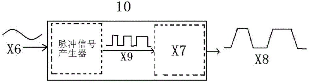
[0030] as the picture shows, figure 1 It is a signal circuit diagram of a Class D audio power amplifier applicable to the present invention. The audio input signal X6 is sent to the class D audio power amplifier 10, and the pulse signal X9 is generated by the pulse signal generator. X9 is sent to the driver and power tube X7, and outputs trapezoidal wave X8, where the duty cycle of X8 represents the strength of the input signal. Since the invention acts on a switched output stage, it is suitable for both PWM and PFM modulation.

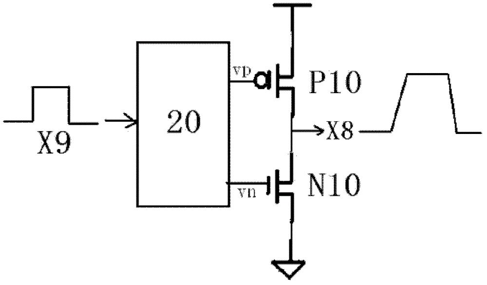
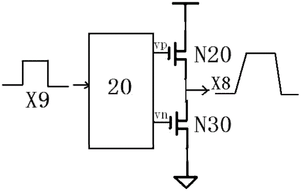
[0031] figure 2 It is the output stage type of the D-class audio power amplifier applicable to the present invention, using complementary power MOSFETs, the input pulse signal X9 is sent to the driver 20 of the power tube grid, and the driver 20 drives the power tubes P10 and N10 to generate the output signal X8. image 3 It is another output stage type of the Class D audio power amplifier applicable to the present invention, adopts all N-type pow...


PUM


Abstract

The invention discloses a driver for a power tube grid of a Class D audio power amplifier. The power tube grid is driven by means of complementary current sources. The driver can ensure that the capability of driving the grid of a power tube is consistent so as to ensure that the variation rate of output pulse signals is consistent no matter the output current is high, low, positive or negative. Thus, the driver ensures lower electromagnetic interference and can reduce the errors caused by higher variation rate of output signals, and the aim of reducing the total harmonic distortion as much as possible while reducing the electromagnetic interference is achieved.

Description

technical field [0001] The invention relates to a driver for a power tube grid, in particular to a driver for a power tube grid of a class D audio power amplifier. Background technique [0002] Class D amplifiers have considerable advantages in terms of power efficiency compared to linear audio amplifiers such as Class A, Class B, and Class AB. For linear amplifiers such as Class AB, the bias components and linear operation of the output transistors dissipate significant power. And because the power output stage of the class D audio power amplifier adopts the switching mode to control the direction of the current flowing through the load, so the static power consumption is very small, and higher efficiency can be achieved. The power consumption of the amplifier is mainly dissipated in the form of heat, so the requirements for heat dissipation of the class D amplifier are greatly reduced. battery life. Class D audio power amplifiers are ideal for compact, high-power applic...

Claims


Application Information

Patent Timeline
Patent Type & Authority Patents(China)
IPC IPC(8): H03F3/217
Inventor 赵玉月黄武康代军杨志飞马琳沈世龙张伟周长胜殷明
Owner JIAXING HEROIC ELECTRONICS TECH
Why Eureka
Try Eureka