
Thin film manufacturing method and manufacturing device

A production method and a technology for producing a device, which are applied to a device for coating liquid on a surface, a spray device, a spray device, etc., can solve problems such as performance degradation

Inactive Publication Date: 2013-01-23
FUJIFILM CORP
View PDF64 Cites 3 Cited by
  • Summary
  • Abstract
  • Description
  • Claims
  • Application Information

AI Technical Summary

Problems solved by technology

[0008] On the other hand, multilayer structural elements are prone to performance degradation due to problems such as energy barriers in the interface between layers

Method used


Image

  • Thin film manufacturing method and manufacturing device
  • Thin film manufacturing method and manufacturing device
  • Thin film manufacturing method and manufacturing device

Examples


Embodiment 1

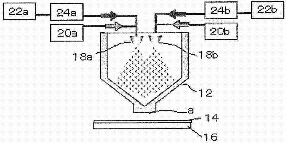
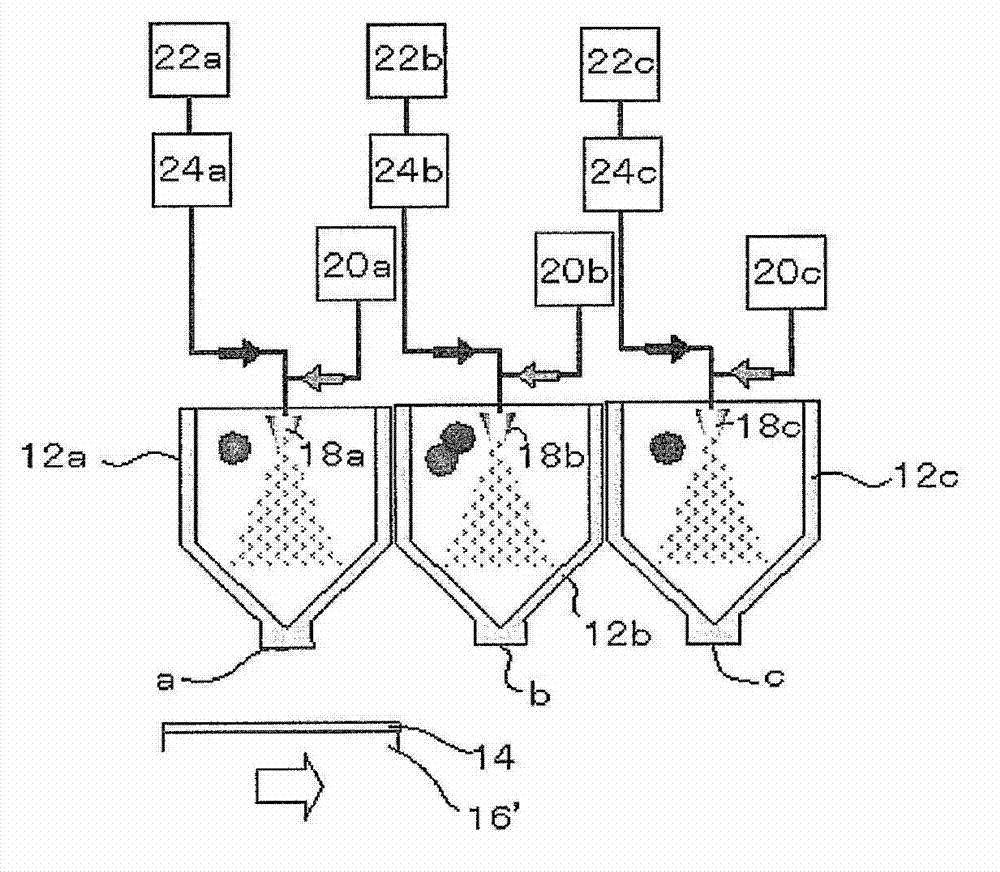
[0304] In Example 1, use and image 3 A film forming apparatus having the same configuration.

[0305] First, the substrate is fixed below the opening a of the chamber 12a, and the raw material solution 1 is sprayed from the two-fluid nozzle 18a in the chamber 12a for 4 minutes to form a lower layer on the substrate, and then the substrate is moved to the opening of the chamber 12b. b, the raw material solution 3 is sprayed from the two-fluid nozzle 18b for 4 minutes to form a mixed layer on the lower layer, and finally, the substrate is moved to the opening c of the chamber 12c, and the raw material solution 2 is sprayed from the two-fluid nozzle 18c in the chamber 12c, An upper layer was formed on the mixed layer to produce a laminated film. The thickness of the formed film was about 0.1 μm.

Embodiment 2

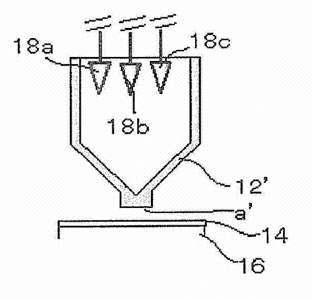
[0307] In Example 2, using figure 2 A film forming apparatus having the same configuration.

[0308] First, the raw material solution 1 is sprayed from the two-fluid nozzle 18a in the chamber 12' for 4 minutes to form a lower layer, then the raw material solution 3 is sprayed from the two-fluid nozzle 18b for 4 minutes to form a mixed layer, and finally, the raw material is sprayed from the two-fluid nozzle 18c Liquid 2 formed the upper layer and produced a laminated film. Meanwhile, the substrate does not move. The thickness of the formed film was about 0.1 μm.

Embodiment 3

[0310] In Example 3, use and Figure 4 A film forming apparatus having the same configuration.

[0311] First, the substrate was fixed below the opening of the chamber 12a', and the raw material solution 1 was simultaneously sprayed for 3 minutes from the three two-fluid nozzles 18a1, 18a2, and 18a3 in the chamber 12a' to form a lower layer on the substrate. Next, while moving the substrate to the lower portion of the opening of the chamber 12b', the raw material solution 1 is sprayed from the two two-fluid nozzles 18b1 and 18b2 in the chamber 12b' for 3 minutes, and the remaining two-fluid nozzle 18b3 is sprayed for 3 minutes. Raw material solution 2. Then, while moving the substrate to the lower portion of the opening of the chamber 12c', the raw material solution 1 is sprayed for 3 minutes from one two-fluid nozzle 18c1 in the chamber 12c', and the two two-fluid nozzles 18c2 and 18c3 are sprayed for 3 minutes. Raw material solution 2. In doing so, a mixed layer is formed...


PUM

PropertyMeasurementUnit
thicknessaaaaaaaaaa
affinityaaaaaaaaaa
thicknessaaaaaaaaaa

Abstract

Provided is a method for manufacturing a multilayer thin film whereby energy barrier effects due to the interface between each layer are mitigated. The method for manufacturing the thin film includes: a bottom layer forming step for forming a bottom layer containing a solute A, wherein, (1) droplets are formed by spraying a raw liquid formed by dissolving and / or dispersing a solute in a solvent, (2) the solvent in the droplets is volatilized and condensed, and (3) a thin film is formed by depositing the condensed droplets on a substrate or on a thin film disposed on a substrate, performed in that order; a top layer forming step for forming a top layer containing a solute B on the bottom layer, wherein the abovementioned steps (1) to (3) are performed sequentially; and a mixed layer forming step for forming a mixed layer containing the solutes A and B, wherein the abovementioned steps (1) to (3) are performed sequentially between the bottom layer forming step and the top layer forming step.

Description

technical field [0001] The present invention relates to a production method of a thin film that can be used in various devices such as organic electroluminescent elements and solar cells, and various optical members such as reflectors and polarizers, and a production apparatus for the thin film. Background technique [0002] With the expansion of networks and the diversification of lifestyles in recent years, electronic devices are required to add value that was difficult to achieve with flexible or large-area conventional Si semiconductors, and organic electronic devices that can be formed on thin films are attracting attention. [0003] In various organic devices such as organic electroluminescent elements and solar cells, it is important to form organic thin films with different functions by laminating them in order to improve performance. As a method for producing a thin film, dry processes such as a vacuum deposition method and wet processes such as a spin coating metho...

Claims


Application Information

Patent Timeline
Patent Type & Authority Applications(China)
IPC IPC(8): B05D1/02B05B1/24B05B7/04B05B7/16B05B7/24H01L51/50H05B33/10
CPCH01L51/56H01L2251/5346B05D1/36H01L51/0004H10K71/13H10K2101/80
Inventor 冲和宏安藤广敏
Owner FUJIFILM CORP
Learn More