Supercharge Your Innovation With Domain-Expert AI Agents!

Metal cap and bottle with cap

A metal cover and liner technology, applied in the field of metal covers, can solve the problems of liner falling off, time-consuming and laborious processing, liner wear, etc., and achieve the effects of smooth insertion, smooth grip, and prevention of falling off

Active Publication Date: 2014-12-17
ALTEMIRA制罐株式会社
View PDF4 Cites 1 Cited by
  • Summary
  • Abstract
  • Description
  • Claims
  • Application Information

AI Technical Summary

Problems solved by technology

That is, when the liner closely attached to the mouth of the bottle is not completely peeled off from the mouth of the bottle when the cap is opened, and the liner is pulled downward relative to the cap in the state of close contact, as in the technique of the above-mentioned Patent Document 1, When the gasket is locked by the lower protrusion of the vent hole, the outer peripheral edge of the gasket may catch the tip of the lower protrusion as the broken part, causing the entire gasket to warp. Detachment causing liner to fall off
In addition, even if it does not fall off, the outer peripheral part of the gasket rubs against the edge of the lower protrusion of the vent hole, so that a smooth feeling cannot be obtained when opening, and sometimes the gasket is slightly worn
Furthermore, in the technique of the above-mentioned Patent Document 2, if the spacer is inserted after forming the slit and the concave portion as the vent hole, the liner may be caught on the front end of the upper protrusion of the slit as the broken portion and become damaged. Unable to insert smoothly, or damage the liner due to friction
Therefore, it is necessary to form the slits and recesses as air vents after arranging the gasket on the inner surface of the top plate in advance, which takes a lot of time and effort in the processing process of the cap.

Method used


Image

  • Metal cap and bottle with cap
  • Metal cap and bottle with cap
  • Metal cap and bottle with cap

Examples


Embodiment

[0041] Next, metal caps and capped bottles according to the present embodiment were actually produced, and the drop-off of the liner at the time of cap opening was evaluated.

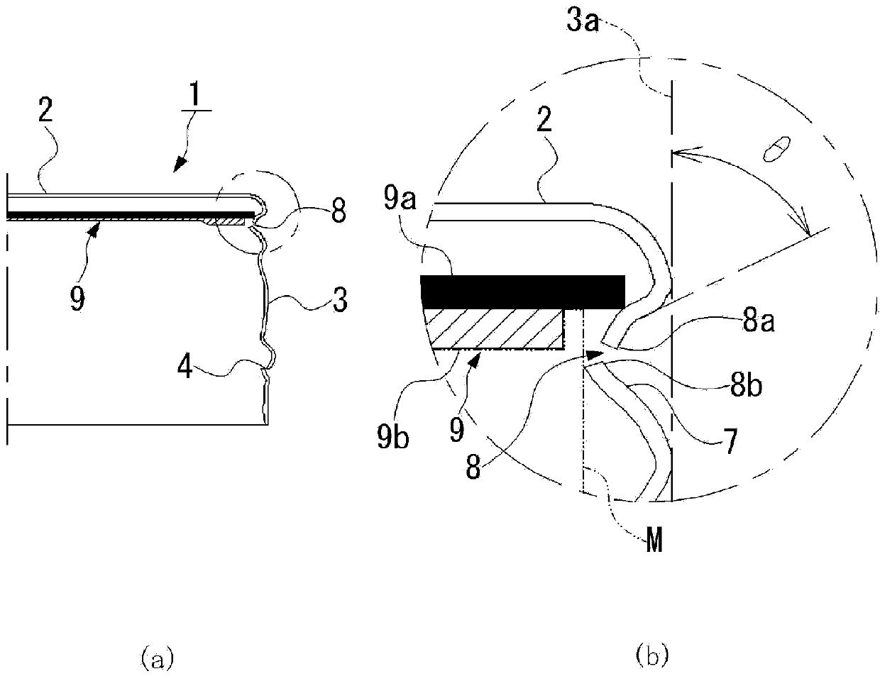
[0042] First, when the angle θ of the upper protrusion of the scored slit was varied from 0 to 87° and manufactured, the opened metal cap was visually evaluated, and the upper protrusion and the lower protrusion separated from the liner The number of parts (hereinafter referred to as hooks) and the number of bottles (hereinafter referred to as the number of cans) investigate the frequency of hook detachment and judge whether it is good or bad.

[0043] In addition, the above-mentioned hook detachment frequency is calculated by the following formula. Hook detachment frequency = (number of detached hooks × number of tanks) ÷ number of evaluation tanks, for example, the number of evaluation tanks is 30 tanks, two out of two tanks have detached hooks, three out of three tanks have detached hooks, and three...


PUM


Abstract

Disclosed are a metal cap and bottle with a cap, which prevent a liner from falling out when the bottle is opened and enable smooth bottle opening and liner insertion. The metal cap (1) comprises a top plate section (2) disposed in the upper section, and a cylindrical section (3) that substantially hangs from the rim of the top plate section and seals an opening of a bottle after the liner (9) has been inserted onto the inner surface of the top plate section in a non-adhered state. The cylindrical section has: a vent hole (8) in the vicinity of the top plate section, that forms a slit-shaped opening in the peripheral direction and releases internal pressure when the bottle is opened; and a top protruding section (8a) and a bottom protruding section (8b) that are formed by bending the upper opening end and the lower opening end of the vent hole (8) inward in the radial direction of the cylindrical section. The end of the top protruding section is positioned further inwards in the radial direction than the outer rim of the liner when the liner is inserted and is also in the same position in the radial direction as the end of the bottom protruding section or positioned further outwards in the radial direction than said end.

Description

technical field [0001] The present invention relates to a metal cap for tightly closing the mouth of a bottle used for beverages and the like, and a bottle with a cap attached to the metal cap. Background technique [0002] Conventionally, in a cap attached to the mouth of a bottle made of metal such as steel or aluminum alloy, there is known a vent hole for releasing the internal pressure when the cap is opened by rotating the cap to release the gas inside the bottle body to the outside. (Also known as scoring slits or vent slits) are formed near the upper end of the cap. For example, Patent Document 1 discloses a cap comprising a cap body having a plurality of protrusions protruding from the inner surface of the skirt wall near the top wall; The gasket disposed on the inner side of the top wall is provided with a cut-in portion around the cover main body, and the cut-in portion is pressed to the inside of the cover to be bent to form the above-mentioned protrusion. In su...

Claims


Application Information

Patent Timeline
Patent Type & Authority Patents(China)
IPC IPC(8): B65D51/16B65D41/34B65D53/00
CPCB65D51/1688B65D41/348B65D41/045B65D53/04B21D51/446B65D51/1694
Inventor 武藤英泰井田宗孝山本荣治
Owner ALTEMIRA制罐株式会社
Features
  • R&D
  • Intellectual Property
  • Life Sciences
  • Materials
  • Tech Scout
  • Unparalleled Data Quality
  • Higher Quality Content
  • 60% Fewer Hallucinations
Learn More