Supercharge Your Innovation With Domain-Expert AI Agents!

Web center position control device, method and program, and web trimming device

A center position and control device technology, applied in the direction of shearing device, use feedback control, manufacturing tools, etc., can solve difficult problems such as the control of plate and strip snakes

Inactive Publication Date: 2015-03-11
NIRECO CORP
View PDF8 Cites 0 Cited by
  • Summary
  • Abstract
  • Description
  • Claims
  • Application Information

AI Technical Summary

Problems solved by technology

Therefore, if something like Figure 13 As shown in the strip material trimming device 600, the strip material position detection sensor 530 and the center position controller 510 are arranged at intervals, then a meandering factor occurs between the center position controller 510 and the strip material position detection sensor 530, and it is very likely Difficult to control to prevent plate and strip meandering

Method used


Image

  • Web center position control device, method and program, and web trimming device
  • Web center position control device, method and program, and web trimming device
  • Web center position control device, method and program, and web trimming device

Examples


no. 1 example

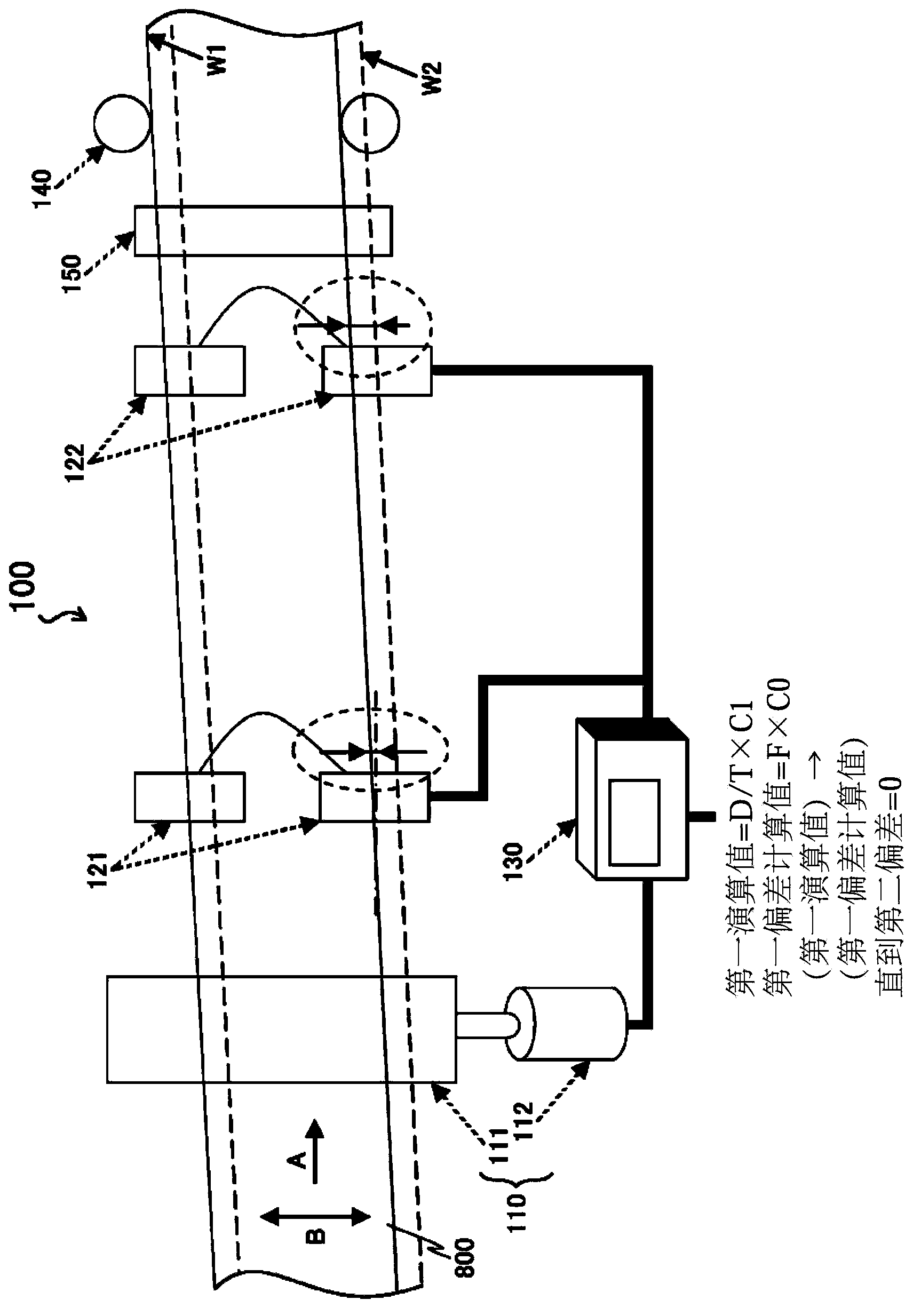
[0086] figure 1 It is a schematic diagram showing the structure of the strip center position control device 100 according to the first embodiment of the present invention.

[0087]The strip center position control device 100 according to the present embodiment includes: a center position controller 110 for controlling the position of the center of the strip 800 conveyed in the direction A from upstream to downstream in the width direction B; A first device for detecting the actual center position of the plate material 800 in the width direction B and sending a detection signal indicating the center position is provided downstream of the center position controller 110 in the conveying direction A of the plate material 800 . Sensor 121; disposed downstream of the first sensor 121 in the conveying direction A of the strip material 800, for detecting the actual center position of the strip material 800 in the width direction B and sending a detection signal representing the cente...

no. 2 example

[0123] In the strip center position control device 100 according to the above-mentioned first embodiment, the second deviation / N (N is a positive integer greater than 2) is added to the first deviation at each control unit time, but in the present embodiment In the strip center position control device, instead of the second deviation / N and the first deviation, the meandering control of the strip 800 is implemented using values ​​calculated from the second and first deviations.

[0124] Figure 5 is a flow chart showing operations performed by the strip center position control device according to the present embodiment.

[0125]After calculating the first and second deviations (step S130), the controller 130 calculates the first calculation value according to formula (1) (step S150), wherein,

[0126] The first calculation value = D / T × C1 (1)

[0127] D: second deviation

[0128] T: value (time) obtained by dividing the distance between the first sensor 121 and the second...

no. 3 example

[0151] The higher the conveying speed of the strip material 800 is, the higher the snaking frequency of the strip material 800 will be, causing the strip material 800 to start to vibrate. When the meandering frequency of the strip 800 is so high, correspondingly, more reliable meandering control of the strip is required. The strip center position control device 200 according to the third embodiment of the present invention described below can reliably perform the strip meandering control even in the case where the meandering frequency of the strip 800 is high.

[0152] Figure 7 It is a schematic diagram showing the structure of the strip center position control device 200 according to the third embodiment of the present invention.

[0153] Compared with the strip center position control device 100 according to the first embodiment, the strip center position control device 200 according to the present embodiment differs only in the operation of the controller 130, and has the...


PUM


Abstract

Disclosed is a web center position control device which is capable of eliminating the offset generated in web conveyance. Specifically disclosed is a web center position control device (100) which comprises a center position control device (110), a first sensor (121) for detecting the actual center position of a web (800) in the widthwise direction, a second sensor (122) for detecting the actual center position of the web in the widthwise direction closer to the downstream side than the first sensor, and a control device (130) for controlling the operation of the center position control device. The control device computes first deviation and second deviation from the detection values of the first sensor and the second sensor, computes a first computing value from the second deviation on the basis of formula (1), and adds the first computing value to the first deviation for each control unit time until the second deviation reaches zero. First computing value = D / T × C1 (1) D: Second deviation T: The value obtained by dividing the distance between the first sensor and the second sensor by the conveyance speed of the web (time) C1: Constant

Description

technical field [0001] The present invention relates to a device for controlling the center position of a strip conveyed in one direction in the width direction (direction perpendicular to the conveying direction), a method for controlling the center position of the strip, and a method for causing a computer to implement the method. Background technique [0002] A device for controlling the center position in the width direction of a strip conveyed in one direction (for example, called a steel plate (strip)) is assembled and used, for example, in a strip trimming machine for trimming the strip . In this plate and strip trimming machine, in order to accurately trim the plate and strip, the central position of the conveyed plate and strip (in the width direction of the plate and strip (the direction perpendicular to the conveying direction of the plate and strip) Center position) or edge position (the position of both edges in the width direction of the plate strip) is essent...

Claims


Application Information

Patent Timeline
Patent Type & Authority Patents(China)
IPC IPC(8): B65H23/038B23D19/06
CPCB65H23/038B65H2404/161B23D19/06G05D3/20B65H2511/20B65H2220/03B65H2220/02B65H43/04G05D3/12
Inventor 太田佳孝今義秋
Owner NIRECO CORP
Features
  • R&D
  • Intellectual Property
  • Life Sciences
  • Materials
  • Tech Scout
  • Unparalleled Data Quality
  • Higher Quality Content
  • 60% Fewer Hallucinations
Learn More