Supercharge Your Innovation With Domain-Expert AI Agents!

A motor rotor assembly structure

A technology of assembly structure and motor rotor, applied in the direction of magnetic circuit shape/pattern/structure, electromechanical device, electrical components, etc., can solve the problem that the keyway cannot be processed symmetrically, reduce the strength of the shaft, increase the processing capacity of the shaft, etc. die cost, reduce total cost, and ensure the effect of accuracy

Active Publication Date: 2020-05-22
HEFEI JUYI POWER SYST CO LTD
View PDF5 Cites 0 Cited by
  • Summary
  • Abstract
  • Description
  • Claims
  • Application Information

AI Technical Summary

Problems solved by technology

This structure requires a key to be designed on the punching sheet, and a key groove to be machined on the shaft. Due to the difference in the angle of inclination, and limited by the influence of the space of the shaft diameter, the key groove cannot be processed symmetrically in the axial direction.
Such a structural design has the following disadvantages: 1) There are multiple key slots on the motor shaft, which will increase the machining volume of the shaft, and at the same time, multiple slots will reduce the strength of the shaft; 2) The key slots on the shaft are limited by the structural space. It cannot be processed symmetrically, and it is difficult to ensure that the center of gravity after final processing does not shift in design, so as to ensure the accuracy level of rotor dynamic balance; 3) The keyway is opened on the motor shaft, and the hollow shaft design cannot be realized through low-cost technology, only through Machining method guarantee

Method used


Image

  • A motor rotor assembly structure
  • A motor rotor assembly structure
  • A motor rotor assembly structure

Examples


Embodiment

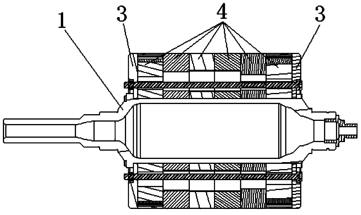
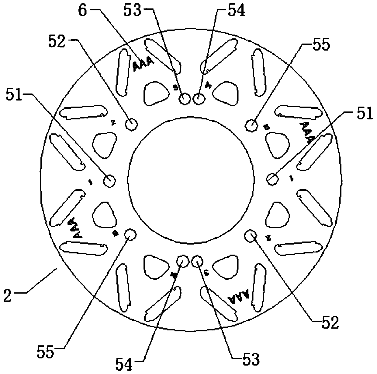
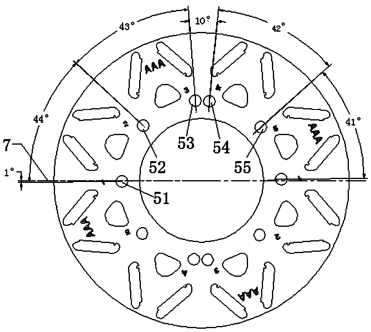
[0021] as attached Figure 1~2 As shown, a motor rotor assembly structure includes a rotating shaft 1, six rotor cores 4 formed by neatly stacking a plurality of rotor punches 2, and two rotor cores installed at the front and rear ends of the whole body composed of six rotor cores 4. Rotor pressing plate 3, the axial middle part of the rotor iron core is provided with a shaft hole for installing the rotating shaft 1, and the two rotor pressing plates 3 are used to compress a plurality of rotor punching plates 2; the rotating shaft 1 is a hollow shaft; The rotor punches 2 have the same structure; each rotor punch 2 has multiple sets of positioning holes; multiple rotor punches 2 are positioned and fixed on the rotating shaft 1 through multiple sets of positioning holes to realize the rotor segment between oblique poles. Each group of positioning holes is composed of two positioning holes symmetrical to the axis of the rotor punching sheet; there are five groups of positioning ...


PUM


Abstract

The invention discloses a motor rotor assembly structure, which includes a rotating shaft, a plurality of rotor iron cores formed by neatly stacking a plurality of rotor punches, and rotor pressure plates installed at the front and rear ends of the rotor iron core. There is a shaft hole for installing the rotating shaft, and two rotor pressing plates are used to compress multiple rotor punches; the rotating shaft is a hollow shaft; multiple rotor punches have the same structure; each rotor punch has multiple sets of positioning holes; Through multiple sets of positioning holes, multiple rotor punches are positioned and fixed on the rotating shaft to realize skew poles between rotor segments. The rotor assembly structure of the motor is formed by laminating one type of rotor punches, which reduces the types of rotor punches and lowers the mold opening cost of punched rotors; there is no need to open key slots on the shaft, and the hollow shaft can be realized through a variety of low-cost processes Design requirements, reducing the overall weight of the motor while saving materials; and ensuring that the center of gravity of the motor rotor assembly will not shift, thereby ensuring the rotor dynamic balance accuracy.

Description

technical field [0001] The invention relates to a motor structure, in particular to a motor rotor assembly structure. Background technique [0002] In the prior art, in the common motor rotor structure, a rotor punch cooperates with a plurality of slots with different angles on the shaft to ensure the oblique poles between the rotor segments. This structure requires a key to be designed on the punching plate, and a key groove to be machined on the shaft. Due to the difference in the angle of inclination and the limitation of the space of the shaft diameter, the key groove cannot be processed symmetrically in the axial direction. Such a structural design has the following disadvantages: 1) There are multiple key slots on the motor shaft, which will increase the machining volume of the shaft, and at the same time, multiple slots will reduce the strength of the shaft; 2) The key slots on the shaft are limited by the structural space. It cannot be processed symmetrically, and i...

Claims


Application Information

Patent Timeline
Patent Type & Authority Patents(China)
IPC IPC(8): H02K1/22
CPCH02K1/22H02K2213/03H02K1/2766H02K1/276H02K1/28
Inventor 刘蕾范佳伦孙纯哲李跃华崔景伟
Owner HEFEI JUYI POWER SYST CO LTD
Features
  • R&D
  • Intellectual Property
  • Life Sciences
  • Materials
  • Tech Scout
  • Unparalleled Data Quality
  • Higher Quality Content
  • 60% Fewer Hallucinations
Learn More