Magnet roller

A magnetic roller and magnetic force technology, applied in the direction of magnets, magnetic objects, permanent magnets, etc., can solve the problem of limited range of resin selection, and achieve the effects of excellent reusability, simple manufacturing process and good environment

Inactive Publication Date: 2015-03-25
P M GIKEN
View PDF6 Cites 0 Cited by
  • Summary
  • Abstract
  • Description
  • Claims
  • Application Information

AI Technical Summary

Problems solved by technology

[0016] Moreover, the magnetic field is added to the resin magnet material during molding, and the magnetic powder in the material is oriented to help increase the magnetic force of the magnetic pole. However, there are also requirements for the binder resin to effectively carry out this orientation through extrusion molding. The problem that the range of choice of resin is limited due to the special thermal melting trend

Method used


Image

  • Magnet roller
  • Magnet roller
  • Magnet roller

Examples


no. 1 Embodiment approach

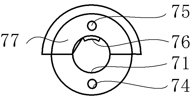
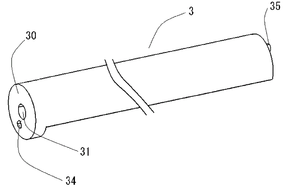
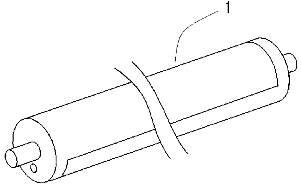
[0055] Such as figure 1 As shown, the magnet roller 1 according to the first embodiment of the present invention is composed of a single metal shaft member 4 and a pair of first and second semicylindrical resin magnet members 2 and 3 shorter than the metal shaft member 4 . Such as image 3 , Figure 5 As shown, the semi-cylindrical resin magnet parts 2 and 3 have the same shape and size as each other, and are respectively formed by injection molding into elongated split cylinders. On each end of these parts 2 and 3, a 1st and 2nd annular part 20,30. First and second center holes 21 and 31 are respectively penetratingly provided at the centers of these annular parts 20 and 30 . Such as image 3 As shown, a semicircular cavity 22 is formed inside the semicylindrical resin magnet part 20 . Although not shown, semicircular cavities having the same shape and size are also formed in the semicylindrical resin magnet member 30 . The first and second center holes 21 and 31 commun...

no. 2 Embodiment approach

[0068] A magnet roller according to a second embodiment of the present invention will be described. Such as Figure 11 As shown, the magnetic roller 5 of the second embodiment of the present invention is the same as the magnetic roller of the first embodiment of the present invention described above, and consists of a pair of first and second semicylindrical resin magnet members 6, 7 and a single metal shaft member. 8 composition. And assembled by a pair of semi-cylindrical resin magnet parts 6, 7 sandwich the metal shaft part 8, the three parts are fitted together and integrated, the support parts 81 at both ends of the metal shaft part 8 protrude from the circle of the resin magnet part. Tubular roller.

[0069] On a pair of semi-cylindrical resin magnet parts 6, 7, such as Figure 12 , Figure 14 , Figure 16 , Figure 18 As shown, the first and second annular portions 60 and 70 are integrally provided at one end portion of each of the elongated split cylinders. The ...


PUM


Abstract

A magnet roller according to the present invention comprises: a single metal shaft member; and a pair of first and second semicylindrical resin magnet members each of which is shorter than the metal shaft member and has a first or second annular portion integrally provided at one end portion thereof. Each of first and second central holes is provided at the center of each of the first and second annular portions. The magnet roller according to the present invention is assembled by arranging the first annular portion and the second annular portion so as not face each other, inserting both end portions of the metal shaft member into the first and second central holes from the inner side of the first and second annular portions, and sandwiching the metal shaft member between the first and second semicylindrical resin magnet members in such a manner that both the end portions of the metal shaft member protrude to the outside of the first and second annular portions.

Description

technical field [0001] The present invention relates to a magnet roller used in a developing device and a cleaning device in image forming devices such as printers, copiers, and facsimile machines that use toner to form images. Background technique [0002] In image forming apparatuses such as printers, copiers, and facsimiles that form images with toner made of powder, a magnetic roller having a plurality of magnetic poles in the circumferential direction is used in a developing device and a cleaning device. The magnetic roller used in the developing device develops the electrostatic latent image formed on the surface of the photosensitive drum with charged toner, and the magnetic roller used in the cleaning device removes the charged toner remaining on the surface of the photosensitive drum. [0003] Regarding the magnet roller, Patent Documents 1, 2, and 3 describe examples in which two semicylindrical resin magnets are bonded to form a cylindrical magnet roller. That is...

Claims


Application Information

Patent Timeline
Patent Type & Authority Patents(China)
IPC IPC(8): G03G15/09G03G15/00G03G21/10H01F7/02
CPCH01F7/0221G03G15/0921
Inventor 小谷节男井田清荻野和彦
Owner P M GIKEN
Why Eureka
Try Eureka