Power tool and operation method thereof

A technology of power tools and operation methods, applied in the field of power tools, can solve the problems of time-consuming and laborious, cumbersome operation, etc., and achieve the effects of improving work efficiency, quick installation or disassembly, and preventing slippage

Active Publication Date: 2013-01-30
POSITEC POWER TOOLS (SUZHOU) CO LTD
View PDF6 Cites 49 Cited by
  • Summary
  • Abstract
  • Description
  • Claims
  • Application Information

AI Technical Summary

Problems solved by technology

[0004] However, the current multi-function machine still adopts the relatively original way of installing the working head, that is, the fastening bolt is loosened by a wrench, and then the fastening element is removed from the output shaft; similarly, in the installation and replacement of accessories, In the same way, the fastening bolt needs to be loosened with the help of a wrench to replace the working head and tighten the installation. The operation is very cumbersome and time-consuming.

Method used


Image

  • Power tool and operation method thereof
  • Power tool and operation method thereof
  • Power tool and operation method thereof

Examples


specific Embodiment approach 1

[0095] The power tool involved in this embodiment is specifically a swing-type power tool, also known as a multi-function machine. But the present invention is not limited to an oscillating power tool, but may also be a rotary abrasive power tool, such as a sander or an angle grinder.

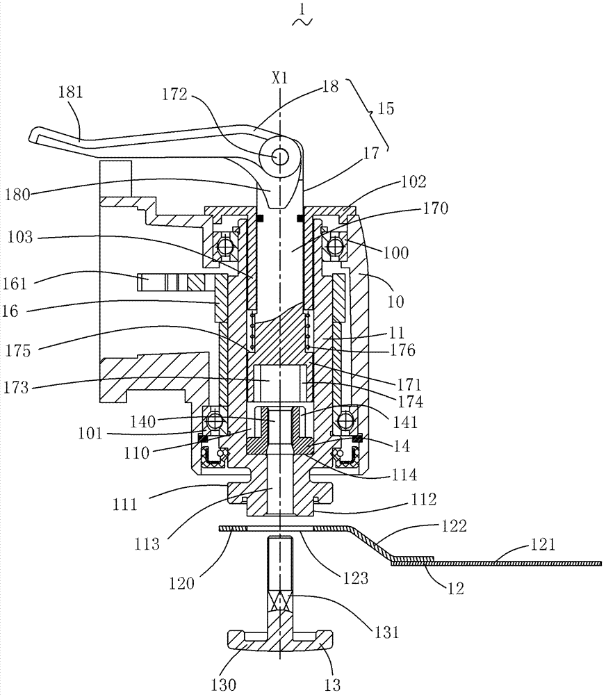
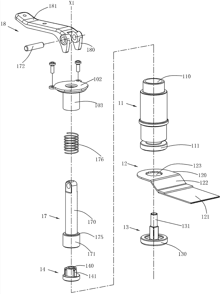
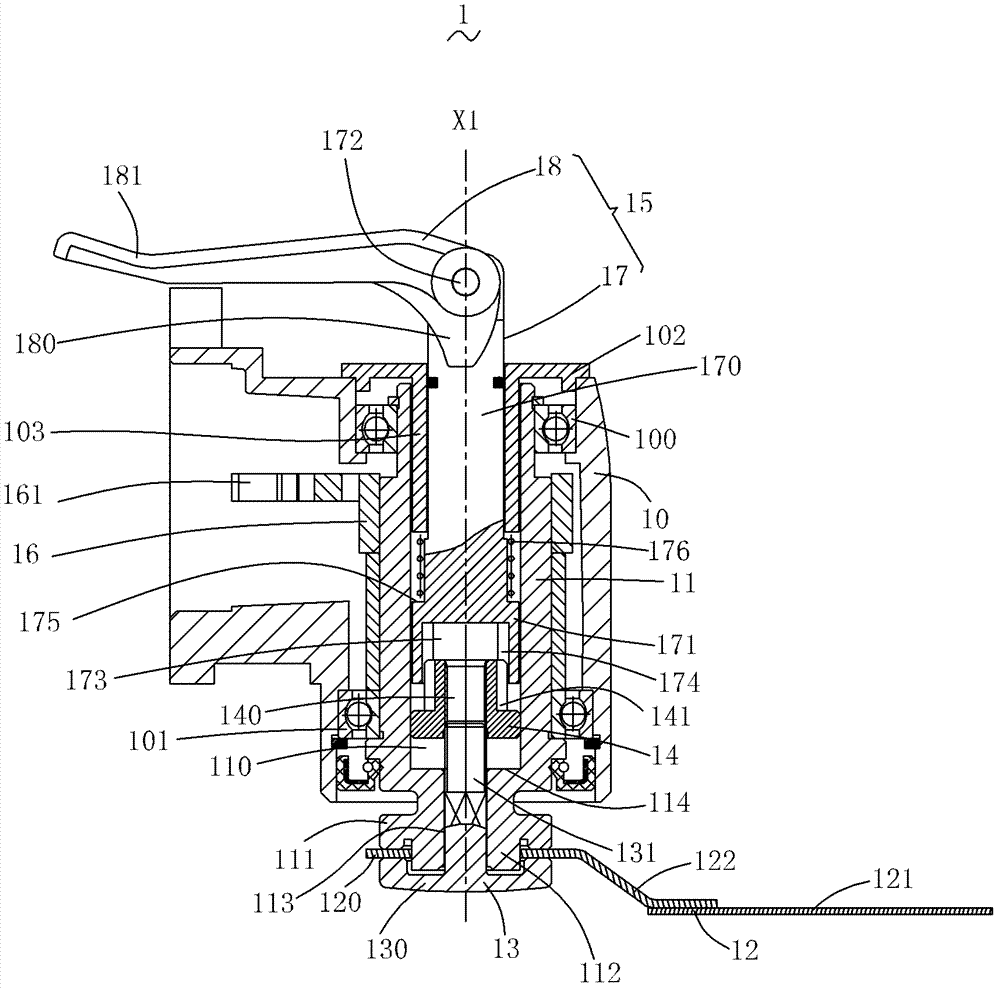
[0096] figure 1 Shown is the head area of ​​the multifunctional machine 1 in this embodiment. The multifunctional machine 1 has a housing 10, an output shaft 11 extending from the inside of the housing 10, a working head 12 installed at the end of the output shaft 11, A locking piece 13 for fixing the working head 12 on the end of the output shaft 11 , a locking piece 14 supported in the output shaft 11 , and a driving mechanism 15 rotatable around the axis X1 of the output shaft 12 . When the driving mechanism 15 is rotated in one direction, the locking member 14 and the locking member 13 can be driven to be threaded and locked; then when the driving mechanism 15 is rotated in the opposite di...

specific Embodiment approach 2

[0123] Such as Figure 7 to Figure 10 As shown, the second embodiment of the present invention discloses an oscillating power tool, that is, a multi-function machine 2, the multi-function machine 2 includes a housing 20, an output shaft 21 installed in the housing 20, and an output shaft 21 inserted into the The locking piece 22, the working head 23 clamped between the locking piece 22 and the output shaft 21, the locking piece 24 accommodated in the output shaft 21 and used to lock the locking piece 22, and the locking piece 24 for driving A drive mechanism 25 rotating around the axis X2 of the output shaft 21 .

[0124] Such as Figure 7 and Figure 8 As shown, compared with the multifunction machine 1 in the first embodiment, the drive mechanism 25 has a different structure. The driving mechanism 25 specifically includes an operating assembly 26 and a driving assembly 27 , and the operating assembly 26 is operable to drive the driving assembly 27 to rotate. Wherein, the...

specific Embodiment approach 3

[0129] Combine below Figure 11 Briefly introduce the third embodiment of the present invention, specifically a multifunctional machine 3, including a housing 30, an output shaft 31 installed in the housing 30, a locking piece 32 inserted into the output shaft 31, and a locking piece clamped on the locking piece. 32 and the working head 33 between the output shaft 31, the locking member 34 accommodated in the output shaft 31 and used to lock the locking member 32, and the driving mechanism for driving the locking member 34 to rotate around the axis X3 of the output shaft 31 35. Wherein, the driving mechanism 35 includes an operating assembly 350 and a driving assembly 351 , and the operating assembly 350 is operable to drive the driving assembly 351 to rotate. Compared with the multifunctional machine 2 in the second embodiment, the only difference lies in its locking member 34 .

[0130] The locking member 34 is axially non-movably installed in the output shaft 31 , so as t...


PUM


Abstract

The invention discloses a power tool and an operation method thereof. The power tool comprises a shell, an output shaft, a fixing component, a locking component and a driving mechanism. A working head is mounted on the output shaft, is driven to work by the same, and is provided with a supporting portion extending out of the shell. The fixing component is used for fixing the working head onto the supporting portion of the output shaft. The locking component is supported on the output shaft and used for locking the fixing component. The driving mechanism is rotationally mounted on the shell, rotates along a first direction operably to drive to lock the locking component with the fixing component by threads, or rotates along a direction opposite to the first direction operably to drive to unlock the locking component from the fixing component. The power tool can be used for mounting or demounting the working head quickly without any other auxiliary tools, and can provide high axial pressing force to guarantee against slip off of the working head. The operation method of the power tool is easy and reliable.

Description

technical field [0001] The invention relates to a power tool, especially a hand-held power tool and an operation method thereof. Background technique [0002] The multi-function machine is a common hand-held oscillating power tool in the industry. Its working principle is that the output shaft oscillates around its own axis. Therefore, when the user installs different working heads on the free end of the output shaft, such as straight saw blades, circular saw blades, triangular abrasive discs, and shovel scrapers, a variety of different operating functions can be realized, such as sawing, cutting, etc. , grinding, scraping, etc., to suit different work needs. [0003] Chinese Published Patent Application No. CN101780668A discloses a multifunctional machine, which includes a motor, the motor shaft of which is connected to an eccentric pin, and a bearing is sheathed on the eccentric pin, thereby forming an eccentric wheel structure. When the motor shaft rotates, the eccentri...

Claims


Application Information

Patent Timeline
Patent Type & Authority Applications(China)
IPC IPC(8): B25F5/00B25F3/00
CPCB25F3/00B25B21/00B25F5/00B24B45/006B27B19/006B24B23/022B24B23/04B27B5/32
Inventor 沃伦·布朗哈利·索默格雷厄姆·格哈德顾华李辉卢德安
Owner POSITEC POWER TOOLS (SUZHOU) CO LTD
Why Eureka
Try Eureka