Maintenance support

A technology for maintenance parts and support frames, applied in the field of mechanical tooling, can solve the problems of reduced maintenance efficiency, out-of-control parts falling off, fixed positioning, etc., and achieve the effects of improving maintenance efficiency, facilitating widespread use, and facilitating maintenance

Active Publication Date: 2013-01-30
CHERY AUTOMOBILE CO LTD
View PDF7 Cites 5 Cited by
  • Summary
  • Abstract
  • Description
  • Claims
  • Application Information

AI Technical Summary

Problems solved by technology

[0004] In the process of realizing the present invention, the inventor found that there are at least the following problems in the prior art: use a crane to lift the mechanical parts, so that the maintenance personnel are located below the mechanical parts to maintain them, because the crane cannot fix the mechanical parts. The mechanical parts will shake randomly during the maintenance process. During the maintenance process, some parts may fall out of control from above, which will hurt the maintenance personnel. Many inconveniences, such as drilling cannot be performed accurately, etc., resulting in reduced maintenance efficiency

Method used


Image

  • Maintenance support

Examples


Embodiment 1

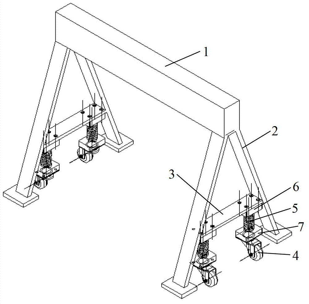
[0014] figure 1 A schematic diagram of the structure of the maintenance bracket of this embodiment is shown. Referring to the diagram, the maintenance bracket of this embodiment includes two parts, namely a support frame and a walking mechanism. The support frame is used to fix the repaired parts and realize the fixation of the repaired parts Positioning is convenient for maintenance personnel to maintain the repaired parts; the running mechanism is arranged at the bottom of the support frame to assist the movement of the support frame, but during the maintenance process of the repaired parts, the positioning of the running mechanism is still to ensure that the support frame and its The parts to be repaired on the machine are all fixed and positioned, so that the maintenance bracket can absolutely fix and position the parts to be repaired and facilitate the maintenance and use of the parts to be repaired at different stations.

[0015] Specifically, the support frame includes:...

Embodiment 2

[0021] The structure of the maintenance bracket provided by this embodiment is similar to that of the first embodiment, the difference lies in the setting of the running mechanism. In the first embodiment, when the roller 4 is set on the positioning plate 3, the spring guide pin 5 is used to realize the supporting frame positioning and walking, in this embodiment, by setting the locking buckle on the roller 4 to replace the spring guide pin structure, when the maintenance bracket needs to move and walk, the locking buckle on the roller 4 can be unlocked, so that the roller 4 touches the ground , make the beam support beam 2 leave the ground, and move the maintenance bracket freely through the action of the roller 4; Positioning of the supporting frame. The structure of the locking buckle is relatively common in the prior art, and will not be further described here.

[0022] The serial numbers of the above embodiments of the present invention are for description only, and do n...


PUM


Abstract

The invention discloses a maintenance support belonging to the field of mechanical tools. The maintenance support comprises a support frame and a travelling mechanism arranged at the bottom of the support frame, a maintained piece is fixed on the support frame, and the travelling mechanism is positioned and fixed when the maintained piece is maintained. Due to the arrangement of the maintenance support with the support frame and the travelling mechanism, the maintained piece can be fixed and positioned on the support frame, a maintenance man can maintain the bottom of the maintained piece conveniently, and as the maintained piece is positioned, the maintained piece can not swing randomly in the maintenance process so as to avoid the potential safety hazard, the safety of the maintenance man is ensured, and the maintaining efficiency is improved; and due to the arrangement of the travelling mechanism, the maintenance support can move conveniently and can be widely used.

Description

technical field [0001] The invention relates to the technical field of mechanical tooling, in particular to a maintenance bracket. Background technique [0002] Mechanical parts such as mechanical operation tools and mechanical molds will be damaged during use, and the damaged mechanical parts can be repaired for further use. If the upper part of the mechanical part is damaged, its maintenance is more convenient. It only needs to be fixed and placed normally, and the upper part can be repaired by the maintenance personnel; It is difficult to approach its lower part to maintain it, and many mechanical parts cannot be turned upside down at will, otherwise it will cause the mechanical parts to be unusable. [0003] In the prior art, when repairing damage to the lower part of a mechanical part that cannot be turned upside down at will, a crane is usually used to lift this type of mechanical part so that the damaged lower structure is located at a position that is convenient for...

Claims


Application Information

Patent Timeline
Patent Type & Authority Applications(China)
IPC IPC(8): B25H1/06
Inventor 丁丽
Owner CHERY AUTOMOBILE CO LTD
Why Eureka
Try Eureka