
Vegetable cutting device

A vegetable cutting device and vegetable technology, applied in metal processing and other directions, can solve problems such as shredding or irregular shape of slices, and achieve the effect of simplifying operation steps

Inactive Publication Date: 2013-01-30
CHINA UNIV OF PETROLEUM (BEIJING)
View PDF6 Cites 5 Cited by
  • Summary
  • Abstract
  • Description
  • Claims
  • Application Information

AI Technical Summary

Problems solved by technology

[0003] The embodiment of the present invention provides a vegetable cutting device to solve the problems of shredded or sliced ​​vegetables such as potatoes and the safety of vegetable cutting

Method used


Image

  • Vegetable cutting device
  • Vegetable cutting device
  • Vegetable cutting device

Examples


Embodiment 1

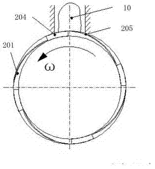
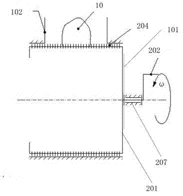
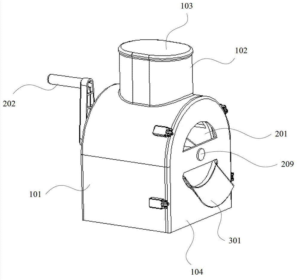
[0030] Such as figure 1 As shown, the vegetable cutting device in this embodiment includes: an outer cylinder 101 and a knife cylinder 201 , and the knife cylinder 201 is arranged inside the outer cylinder 101 and can rotate.

[0031] Such as figure 2 As shown, the outer cylinder 101 includes: a back plate 105 for closing one end of the outer cylinder 101, and a rotating shaft support hole 106 is arranged on the back plate 105; a material inlet 102 is arranged on the wall of the outer cylinder 101 for making the The vegetables put in contact with the knife cylinder 201 .

[0032] Such as image 3 with Figure 4 As shown, the cutter cylinder 201 includes: a support plate 206, which is used to close one end of the cutter cylinder 201, and the center of the support plate is provided with a rotating shaft fixing hole 203; a rotating shaft 207 is arranged along the axis of the cutter cylinder 201, and passes through the rotating shaft The fixing hole 203 is fixedly connected w...

Embodiment 2

[0035] Such as Figure 5 As shown, the vegetable cutting device in this embodiment includes: an outer cylinder 101 , a knife cylinder 201 and a pressing cover 103 , and the knife cylinder 201 is arranged inside the outer cylinder 101 and can rotate. The pressing cover 103 is used for inserting into the feeding port to press the vegetables to the knife barrel 201 . The outer cylinder 101 includes: a back plate, which is used to close one end of the outer cylinder 101, and a rotating shaft support hole is arranged on the back plate; a material inlet 102, which is arranged on the upper end of the wall of the outer cylinder 101, is used to make the put vegetables and the knife Cartridge 201 contacts. Knife cylinder 201 comprises: support plate, is used for closing one end of knife cylinder 201, and the center of support plate is provided with rotating shaft fixing hole; Rotating shaft 207, is arranged along the axis of knife cylinder 201; The cutter cylinder 201 is fixedly conne...


PUM


Abstract

The invention relates to a vegetable cutting device which comprises an outer barrel and a cutter barrel. The cutter barrel is arranged inside the outer barrel and can rotate, the outer barrel further comprises a rear plate and a feeding port, wherein the rear plate is used for closing one end of the outer barrel, a rotation shaft support hole is arranged on the rear plate, and the feeding port is arranged at the upper end of a barrel wall of the outer barrel and used for enabling put vegetables to be contacted with the cutter barrel. The cutter barrel further comprises a support plate, a rotation shaft and a plurality of blades, wherein the support plate is used for closing one end of the cutter barrel, a rotation shaft fixing hole is arranged in the center of the support plate, the rotation shaft is arranged along an axis of the cutter barrel, the rotation shaft is fixedly connected with the cutter barrel through the rotation shaft fixing hole, one end of the rotation shaft penetrates through the rotation shaft support hole of the rear plate to extend to the outer portion of the rear plate, a rotation handle is installed on the rotation shaft outside the rear plate, and the blades comprise transverse blades and longitudinal blades which are fixedly installed on the outer barrel wall of the cutter barrel. A problem that vegetables such as potatoes are irregular in shred or slice and vegetable cutting is not safe is solved.

Description

technical field [0001] The present invention relates to the vegetable cutting tool technology, in particular to a vegetable cutting device. Background technique [0002] In the prior art, the tools for cutting vegetables such as potatoes into shreds or slices are mostly flat shredded shredding tools, which are simple in structure and mostly consist of mesh blades and blade bearing plates. When in use, the user holds the blade carrying plate with one hand, and the other hand holds the potato to shred the potato on the mesh blade. However, this traditional silk wiping tool not only cuts out the rough surface and irregular shape of the silk, but also has the danger of injuring the operator's hands. Contents of the invention [0003] An embodiment of the present invention provides a vegetable cutting device to solve the problems of shredded or sliced ​​vegetables such as potatoes and the safety of vegetable cutting. [0004] The purpose of the present invention is to provide...

Claims


Application Information

Patent Timeline
IPC IPC(8): B26D1/25B26D7/26B26D7/06B26D5/10
Inventor 丁祎丁庆新李庆史新宇张宁池青谢骏遥解飞高岸
Owner CHINA UNIV OF PETROLEUM (BEIJING)
Learn More